Tag - uav

Drone Inspections go nuclear with GPS and RADAR

AsteRx-m2 UASHigh-precision GPS receivers mounted on drones able to identify 1mm hairline defects in cooling towers  

Drones rise to the challenge

How do you inspect a structure that’s almost 160 m high and 120 m in diameter? With a few weeks to spare, a crash course in abseiling and a head for heights, a person could certainly give it a go. Imagine, however, that you need to collect enough data for a 3D model with the precision of 1 mm…all within a week. This was the challenge facing Aetos Drones. The company was tasked with inspecting a cooling tower at Tihange Nuclear Power Station near Liege in Belgium.  

Keeping reactors in top condition

The three reactors at the Tihange Power Station came online between 1975 and 1985. This makes the oldest of the three over 40 years old. Cooling towers built in this era have a life expectancy of 15-20 years. But, with careful maintenance, the lifetime can extend a further 20 years. The Tihange reactors contribute about 25% of all electricity generated in Belgium. The plan is to decommission the towers in 2025. Until then, the cooling towers need to be kept in good working order. Fortunately, drones equipped with highly precise and reliable GPS receivers can help.  

Corrosion and cooling towers

Pressurized Water Reactors, such as at Tihange, have cooling towers. These towers supply cold water to the condenser which works to cool the steam back into water. The steam drives the electricity-generating turbines. Cooling towers are elegantly simple in their operation. Warm water from the condenser sprays into the tower through a network of sprinklers, warming the surrounding air and causing it to rise. This in turn draws cooler air in through openings in the base of the tower maintaining a constant, natural draft of cool air through the tower. Corrosion is a possibility in any system where water plays a part. Cooling towers are hollow, thin-walled structures made from reinforced concrete. Over time, the humid environment can corrode the metal elements of the tower. In every cycle through the cooling tower, about 2% of the water evaporates forming the characteristic steam clouds. This increases the salt concentration in the remaining water which increases its corrosive power. In addition, high winds and winter icing can also cause damage and weaken the cooling tower.  

The inspection

Aetos Drones, were called in to carry out the inspections. And, Belgian's first certified drone pilot, Lieve Van Gijsel, took the helm. An octocopter fitted with a high-resolution camera, a RADAR system and an AsteRx-m UAS receiver conducted the inspection. The air vehicle took photographs at regular intervals as it traveled vertically up and down the sides of the cooling tower. The RADAR system was AIRobot’s Ranger, an add-on sensor specifically designed for distance detection on UAVs. The octocopter needed to get close enough to get quality images. However, the octocopter needed to maintain enough distance so as not to risk getting tossed around by the turbulence generated by the tower.  

Processing the images

Over the course of 4 days, more than 19,000 photographs of the cooling tower were taken. During the flight, the AsteRx-m UAS receiver logged GNSS measurements and the exact time each photograph was taken. After the flight, these shutter times and GNSS measurements were combined with GNSS measurements from a nearby base station using Septentrio’s GeoTagZ software. As such, each photograph was stamped with the cm-level precise RTK position of the camera – the ideal input for the next processing stage. After processing with GeoTagZ, the photographs were then uploaded to the photogrammetry software Agisoft PhotoScan. Over the course of several days, the photographs were stitched together to produce a highly-detailed 3D model of the cooling tower, precise to the level of 1 mm. Experts at Tihange then analyzed the surface of the cooling tower down to any required level of detail.  

Precise yes, but also reliable

3D inspection models with 1 mm resolution are made possible using high-quality, multi-frequency GNSS measurements from high-end receivers like the AsteRx-m. Not only does the positioning have to be precise, it has to be reliable. This requires: accurate error models, continuous tracking during mechanical jolts and advanced satellite integrity monitoring (RAIM). For large-structure inspections, such as this, multi-constellation positioning is essential to ensure there are always enough satellites available to work with. The receiver will also need a good multipath mitigation filter (APME) to disentangle direct and reflected satellite signals to avoid jumps in the calculated position.  

AsteRx-m2 UAS

The AsteRx-m UAS established itself as the receiver of choice for UAV applications requiring high-precision positioning. With the recent release of the  AsteRx-m2 UAS, drone inspections can take on applications at an entirely new level of difficulty. The AsteRx-m2 UAS adds BeiDou and Galileo as well as L5 frequency tracking. It also includes the AIM+ interference mitigation system. The additional constellations allow operation in areas where overhead structures limit the scope of single and dual-constellation receivers. Shop Septentrio's line of high accuracy receivers at Unmanned Systems Source.

MicroPilot Integrates xNAV GNSS/INS into Autopilots for Greater Accuracy

MicroPilot recently announced the completion of work to integrate an OxTS xNAV miniature GNSS/INS system in to their UAV autopilots. The interface allows MicroPilot systems to use the blended GNSS/IMU output of the INS in their flight control system. This integration provides accurate positioning. “We were excited to work together with MicroPilot to develop an interface between our systems," said Iain Clarke, Product Manager from OxTS. "As the UAV market continues to grow people are still discovering ways to take advantage of the platform. We hope this development brings new opportunities to customers looking for integrated systems and UAV navigation options.”  

Designed for commercial UAV mapping

The xNAV is a miniature GNSS/INS system. It is designed for commercial UAV mapping applications that require precise geo-referencing capabilities. For UAV based LiDAR, hyperspectral or thermal mapping, a survey-grade INS is crucial. It provides the accurate trajectory information needed to create 3D pointclouds, digital terrain models, and other maps. INS also enhances photogrammetry applications. In addition, it reduces the need for ground control points, lowers image processing time and removes jumps and gaps in data, saving time from reprocessing to fix errors. While many autopilot systems have integrated GNSS, they are usually lower-grade, single frequency receivers only capable of 1-2 m accuracy. By developing an interface with OxTS systems, MicroPilot autopilots can use the centimeter-level RTK position output of the INS in their flight control system. The autopilot also receives the benefit of INS navigation which is robust and protected against GNSS dropouts. Thanks to the integrated GNSS and IMU in the xNAV, as well as OxTS’ tight-coupling technology, the navigation solution is smooth, resistant to GNSS jumps, and position drift is limited even when fewer than 4 satellites are in view. This can allow UASs to fly and navigate confidently in harsher GNSS environments such as urban canyons, near vegetation, or under bridges. “MicroPilot is pleased to work with OxTS,” said Howard Loewen, President of MicroPilot. “This integration will create a better performing system for our customers.”   Shop MicroPilot's line of autopilots at Unmanned Systems Source.

PingStation makes its debut from manufacturer uAvionix

uAvionix Corporation, the leading Unmanned Aircraft System (UAS) avionics solution provider, recently announced the introduction of PingStation. PingStation is an all-weather, networkable ADS-B receiver for low and high altitude aircraft surveillance. Additionally, it is robust enough to permanently mount outdoors in harsh environmental conditions. It is also small enough for use as a mobile asset for roaming operations.

PingStation debut application

In its debut application, PingStation is a component in Phase 1 of Project UAS Secure Autonomous Flight Environment (U-SAFE). This program is part of a low-altitude Beyond Visual Line of Sight (BVLOS), Unmanned Traffic Management (UTM) corridor. This corridor extends from Griffiss International Airport to Syracuse, NY. A grant from Empire State Development Corporation provides funding for Project U-SAFE. Additionally, PingStation provides ADS-B receiver capability for the Gryphon Sensors Mobile UTM System – Mobile SkyLight.  

Features of PingStation

PingStation is a dual band (978MHz and 1090MHz), networkable ADS-B receiver with a Power-Over-Ethernet (PoE) interface enclosed in an IP67 rated protective enclosure. Integrated is the TSO certified uAvionix FYX GPS receiver for high-resolution time-stamping for critical applications. It provides ground, surface, or low-altitude ADS-B surveillance within line of sight of the antenna, with ranges exceeding 250NM depending on the transmission power. PingStation has multiple uses within the aviation industry:
  • Unmanned Traffic Management (UTM) systems
  • A component of UAS Ground Control Stations (GCS)
  • A component of UAS Detect and Avoid (DAA) systems
  • Airport surface and region situational awareness
  • FBO/flight school fleet tracking and management
Multiple subscription free software/data interface types allow easy integration directly into end applications such as UAS ground control stations, airport surface displays, or cloud-based situational awareness applications. Natively, PingStation provides integration into Virtual Radar Server, an open-source situational awareness mapping display system, the Kongsberg Geospatial IRIS UAS Airspace Situational Awareness Display, and INDMEX Aviation’s Airboss airport situational display suite.
PingStation Range Plot in Virtual Radar Server showing 50NM Range Rings.
“uAvionix is excited to add PingStation to our product line of ADS-B transceivers and receivers,” said Paul Beard, CEO of uAvionix. “Our customers informed us for the need of robust and low-cost surveillance solutions to complement the airborne equipment used in their operations.”   Shop uAvionix entire line of ADS-B products, including the PingStation, at Unmanned Systems Source.  

About uAvionix Corporation

uAvionix develops the world’s smallest, lightest and most affordable ADS-B transceivers, transponders, and GPS receivers. Based in Palo Alto, uAvionix has gathered a cross-disciplinary team of experts in embedded RF engineering, sUAS operations, avionics, hardware, software, and cloud services.

PV Solar Panel Field Inspection with UgCS Mission Planning Software

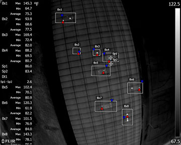
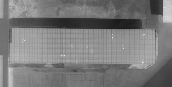
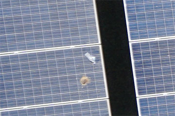
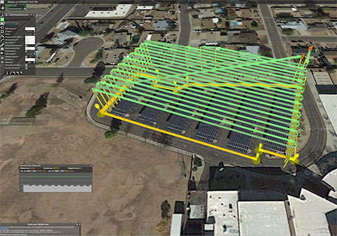
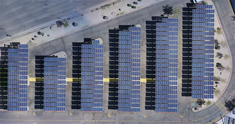
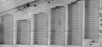
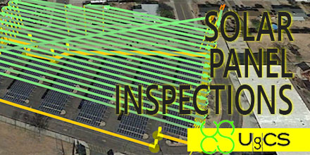
Solar panel fields, like any other artificial infrastructure objects, require periodical inspections. Usually photovoltaic (PV) solar panel field inspection requires use of two sensors - infrared (IR) and daylight cameras, to detect faulty panels. Solar panels may heat up because of connection issues, physical damage or debris. A drone equipped with a thermal camera is the best choice for solar panel field inspection. This method saves costs compared to manned aviation and saves time compared to visual control with handheld IR camera. Semi-professional drones with changeable cameras like DJI Inspire are an option. However, switching out cameras means flight time is doubled. The first is a survey flight conducted with a daylight camera. The flight is then repeated after changing to an IR camera. To minimize time required for inspection usually both sensors (cameras) are used simultaneously. Such a payload requires a drone with enough lift-off capability.  

Detectable defects

The two major defects visible with IR camera are connection issues and physical damage. Connection issues occur, for example, when a panel or a string of panels are not connected to the system. As a result, power produced from the panel(s) cannot flow through the system and on to the grid. That power is converted to heat and the entire panel(s) will heat up slightly.
Figure 1
For example, (see Figure 1) the panel marked Bx7 presents little bit higher average temperature comparing to other panels and should be checked for both - defects and connection issues. Another detectable defect is physical damage to the underlying panel. This causes small areas of more extreme heating as power flows around and backs up behind the damaged area. Such defects are visible on sample - bright point in rectangle marked Bx3 with maximum temperature 169.4 F (76.3 C). Also, physical damages are visible in other zones. Both kind of defects usually are clearly visible on images in IR spectrum what makes defects localisation relatively easy even on stitched orthophoto.  
Figure 2
In visible spectrum, (using daylight camera) usually only debris on panels is detected. This information, though, helps determine if the hotspot is the actual panel heating up or if it is the debris (dirt, bird droppings, etc) heating up.
Figure 3
Glass breaks are usually not detectable unless drone will fly very low as the cracks are small. Only in case of severe damage situations glass breaks will be visible on photos.  

Solar Panel Field Inspection Mission Planning in UgCS

In general, solar panel field inspection missions with drones are planned the same way as standard UAV photogrammetry missions. The survey area is set and the route and camera settings are optimized to obtain the best result for data processing.
Figure 4

GSD selection

For photogrammetry, mission ground sampling distance (GSD) is defined by client and it is the main characteristic of survey’s output data. In case of solar panel inspection client has to define which defects have to be detected. To detect panels with connection issues GSD for IR images should be set 25 cm. To detect physical damage or hotspots smaller than whole panel the GSD should be set from 5-16 cm. For survey missions, when a drone carries IR and daylight cameras simultaneously, the GSD for daylight camera isn’t relevant. This is because it produces pictures with much better GSD than IR sensor because of the low resolution of thermal cameras. For example, an optical camera with a 16 mm lens to match the 7.5 mm FLIR lens will produce images with 1.3GSD while the FLIR images are at 15.7GSD. For solar panel survey missions, when a drone with changeable cameras is used set GSD > 2 cm - this will enable to detect even small debris on panels but will not produce thousands of images from flight.  

Camera position

Mostly camera are set to nadir position. In situations where a tracker system can't be positioned at a set angle or for some fixed array sites – based on the time of the day and sun position oblique setup can be used. Optimal angle of solar panels for thermal images is from 5 to 30 degrees to avoid reflection and inaccurate temperatures. If such images can’t be acquired with nadir camera position, the camera angle has to be adjusted to ensure pictures of panels in range from 5 to 30 degree angle.  

Data processing

Standard image data processing techniques can be used to stitch photos taken with daylight and IR cameras.
Figure 5
Orthophoto maps of relatively small solar panel fields can be analysed manually with different zoom level. To enable rapid evaluation for large fields with millions of panels automated defect detection should be used. Defected panels are marked and further inspections can be accomplished manually.
Figure 6
Without doubt the use of UAV for area surveying or infrastructure inspection saves on both time and cost. Drone mission planning features and tools of UgCS enable UAV professionals to customize each mission according to application requirements.   Find the right UgCS Mission Planner Software that is right for you at Unmanned Systems Source. Article is written in collaboration with Industrial Aerobotics, Arizona-based company providing aerial inspection, surveying and mapping services using UAVs and reprinted with permission.

Aeromapper Talon successfully completes BVLOS mission over 30Km away

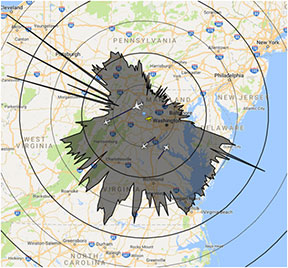
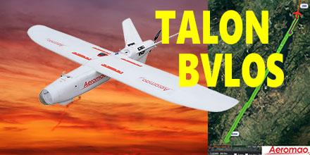
Recently, Aeromao's Aeromapper Talon successfully completed an autonomous mission to a target located 30km away. The Talon maintained strong communications and its control link throughout the entire mission. This mission successfully demonstrated the potential for Beyond Visual Line of Sight (BVLOS) operations for the Talon. The Aeromapper Talon costs only a fraction compared to systems with similar capabilities.  

Aeromapper Talon Demonstrates BVLOS

The Aeromapper team carried out the mission in the Andes Mountains of South America. The location of the flight was situated at 2,800m above sea level. The flight had a cruise altitude of 250m agl. Fifty percent of the flight traversed a body of water. The Talon traveled a total distance of 60km in its one hour flight. With a flight endurance of 2-hours, the Talon had enough flight time left to travel an additional 30km. However, the operators decided to bring the UAV back due to peaks in excess of 3,500 m above sea level in the flight path. Currently, the team is planning a future mission to demonstrate 50km reach capabilities. Aeromao's Aeromapper 300 also uses the same long range communication system as the Talon. The demand for BVLOS missions continues to grow throughout the industry. Applications for such missions include: power line and pipeline monitoring, roadways survey, surveillance and wildlife control, as well as long linear missions.  

Powerful solution for linear mission challenges

"We receive many requests from clients who need to fly linear missions sometimes to survey thousands of kilometers of pipelines, power lines or roadways," said Mauricio Ortiz of Aeromao. "We ourselves have completed hundreds of kilometers of linear projects, and know very well the challenges of these types of operations." The Aeromapper Talon is proving a solid solution given the specific capabilities demanded for these applications. Aeromapper Talon performs well in all:
  • Ability to operate in difficult terrain and with a mobile GCS with reliable and strong communications.
  • Quick deployment and easy operation: the Aeromapper Talon is flight ready in 15 minutes. It is one of the easiest UAVs to operate.
  • Several cycles of takeoff and landings per day from different locations: here the hand-launch and parachute landing are pretty much a MUST have. A large area survey needs the flexibility of operating from virtually anywhere.
  • Reliable and easy to repair in the field, as well as affordable with interchangeable spare parts.
 

Complete UAV solution, multiple fronts

Additionally, the Aeromapper Talon is also a multi-mission payload complete solution. It is a great choice for various applications, such as agriculture, centimeter accurate surveys, surveillance, and monitoring. Payloads available include:
  • 24 Mp RGB + with Parrot Sequoia simultaneously: complete full surveys at high resolution and get vegetation data in a single flight.
  • 24 Mp RG + Thermal Infrared: Ideal for pipeline or wildlife monitoring.
  • Forward looking day / night payload: An affordable surveillance and observation platform with long range video streaming. All systems are easily swappable.
  • Micasense RedEdge: A swappable payload option with serious agriculture power.
  • GNSS PPK: Eliminates GCPs and achieves up to 3 cm of accuracy for engineering projects. Also available as a swappable payload.
  • Pix4DMapper Aeromao Edition: serious post processing power with the most exhaustive power available. In an affordable bundle package with the complete UAV system.
  • Agisfot Photoscan Pro: Affordable and flexible post processing software to become a post-processing Ninja.
  Shop Aeromao's entire line of affordable UAV solutions at Unmanned Systems Source.

PPK vs. RTK: When do you choose one over the other?

PPK vs. RTKUAS vendors targeting markets from commercial survey to agriculture are fielding systems with real-time kinematic GNSS (RTK) capability. In principle, RTK promises accuracies at the 1-3cm level. The main purpose is to minimize or eliminate the need for ground control points, thereby reducing cost. Altavian uses GNSS receivers upgradeable to RTK operation, but favors another approach for this level of accuracy: post-processed kinematic (PPK). There are a couple of reasons why:
  1. RTK requires a GNSS base station equipped with a transmitter with a reliable link to a fairly dynamic moving platform.
  2. The rover (on the UAS) itself requires a dedicated receiver for the corrections.
These primary reasons carry some further implications for the cost of deployment, especially when considered against PPK.  

PPK vs.RTK

RTK operations not only require a stationary base station, but it must be located at a known control point. Provided the base station is deployed for long enough periods of time, this is not too much of a problem. The base station’s precise location can be determined post-mission if no control points are already present. In this case, a global shift of the aircraft’s trajectory must be done once the position of the base station is determined, taking away some of the benefits of a ‘real-time’ solution. PPK requires a base station as well. But in many cases, at least in the Eastern US, the public CORS network may be dense enough to provide a base station reasonably close to your project. But, it’s likely you will need a base station of your own. This represents slightly less investment in an over-the-air link to the rover. However, it comes with the possibility of loss-of-lock.  

Losing Lock

In both RTK and PPK, when the rover loses lock, a new integer ambiguity resolution procedure must be initiated. The advantage of PPK is that the search can proceed from previous and future data relative to that instant. Additionally, forward and reverse solutions in PPK are optimally combined and give an estimate of a solution’s consistency. RTK solutions cannot use data that has not yet been recorded. If you want to eliminate ground control points and you chose an RTK system, there is no external information for basing accuracy estimates. Finally, it is worth noting that antennas light enough to be mounted on a small UAS are not geodetic-grade and are not likely calibrated for phase-center variation (PCV), let alone the actual location of the phase center. This means that you might get a reported solution accuracy of 2cm, but it could easily be very misleading. With a PPK solution, at least you can see if the forward and reverse solutions agree within certain bounds (and we acknowledge this is a very limited vote of confidence for any kinematic solution, but it’s better than nothing).  

Conclusion

Ultimately, there is no replacement for real ground truth, especially if your data product must be certified to a specific level of accuracy. However, strategies to minimize the requirements on GCPs can vary widely in their effectiveness, depending on your needs. If positional accuracies of a few decimeters are acceptable, real-time L-band corrections through a subscription service such as TerraStar-D are very attractive alternatives that require no base stations at all. You can find and shop Altavian's line of solutions at Unmanned Systems Source.