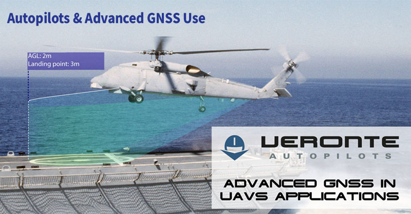
Autopilots and advanced GNSS use types is an important piece to a UAVs functionality.
Obtaining the most accurate information about a UAV's position and attitude -- anywhere in the world and in all weather conditions -- is fundamental.
Therefore, understanding the types and functions of advanced GNSS systems is essential.
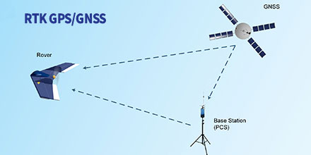
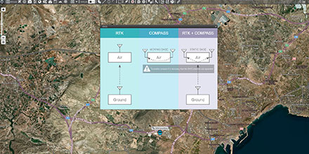
RTK GPS/GNSS Positioning
In Real-Time Kinematic (RTK) mode the UAV calculates its position in relation to the Base position location (GCS). In turn, the base station sends corrections to the GPS/GNSS air module.
This process improves the relative accuracy between both devices; eliminating errors introduced by the atmosphere and other factors.
With RTK positioning activated the relative accuracy improves to the centimetre scale.
Depending on operational needs, operators can activate RTK positioning for the flight duration. Or, operators can automate the function so the drone receives RTK corrections during critical flight phase.
The landing phase is an example. RTK corrections ensure centimetre accuracy at touchpoint time (fixed-wings), landing on an exact point (multi-rotor) or activate in advanced modes (landing on a network or moving vehicle).
One drone application that takes advantage of RTK mode is photogrammetry.
Photogrammetry with drones makes possible to model a 3D surface, create plans and perform measurements. As such, achieving high accuracy is vital.
Drone camera positions with RTK calculate in real-time. This allows correcting camera positions of a few precision centimetres, both vertically and horizontally.
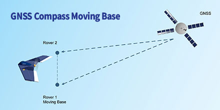
GNSS Compass Moving Base
With this method, a moving vehicles attitude and orientation is estimated without the use of a magnetometer or other sensors sensitive to electromagnetic interference.
For this, a minimum of two GNSS antennas (GPS, Glonass & BeiDou) provide a known relative position between them.
The reference station and mobile receivers can move while calculating a precise vector between the receiver antennas. They calculate the position and the attitude of the vehicle based on the GNSS signal.
Helicopters frequently use this model in order to achieve magnetometer redundancy.
An example of loss orientation is in the vicinity of high voltage towers. Since the electromagnetic interference presence interferes with the magnetometers measurement.
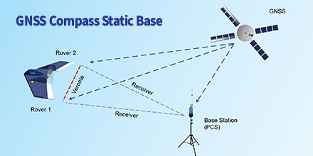
GNSS Compass Static Base
In this model, a fixed base station provides the corrections for the platform orientation.
Plus, the UAV's avionics system can use previously measured coordinates of the antenna position at the base. This guarantees a better absolute drone position.
Knowing the two vectors between the base and each UAV antennas, the avionic system calculates the vector between the two air antennas.
Uses include landing on mobile platforms such as ships.
As such, the accuracy of the mobile platform is much greater when communicating orientation corrections through the fixed base.
GNSS Use in Veronte Autopilot
Veronte Autopilot incorporates all these types of GNSS use without the need to integrate any additional hardware.
A double GNSS sensor (GPS, Glonass & BeiDou) -- on the ground and in the air -- can activate from Veronte PIPE software. The activation is done in a simple way with the wizard created for the different scenarios.
At Embention, our team of Engineers continuously incorporate the latest technology into our autopilots.
Veronte Autopilot features a navigation system that -- regardless of location and weather -- provides high accuracy information about the position and attitude of the drone.
Delivering high accuracy with GNSS, is it possible? Let’s say you need reliable accurate global positioning in your technology. You do some research and decide a multi-frequency GPS/GNSS[1] receiver is the solution. So, you order an evaluation kit.
Now, how do you get your receiver to deliver the high accuracy that it promises?
GNSS receivers rely on external corrections to compensate for various imperfections called GNSS errors to achieve decimeter or even centimeter level accuracy as fast as possible.
Correcting GNSS errors
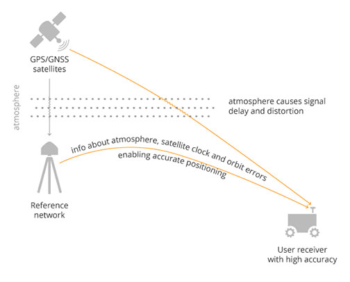
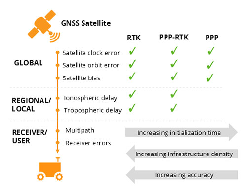
GNSS based positioning is calculated using a method which, by itself, is limited in accuracy. The accuracy limitations are due to several errors caused by GNSS satellites as well as the Earth’s atmosphere.
GNSS satellites are essentially highly accurate synchronized clocks orbiting the Earth. These satellites constantly broadcast their positioning and timing information.
A GNSS user receiver gets signals from several of these “flying clocks” and calculates its distance to each satellite. When the receiver knows the distance to at least four satellites it can deduce its own position.
However, certain errors affect the accuracy of this position.
Even advanced clocks on board GNSS satellites experience minute drifts which cause clock errors.
As GNSS satellites orbit the Earth, their movement along the path is predictable. However, these predictions are not ideal, which results in what’s called orbit errors.
Plus, satellite equipment also introduces small signal errors. They model these errors as satellite biases.
Atmospheric errors
Additionally, there are atmospheric errors. As the signal passes through the Earth's ionosphere (outer layer) and troposphere (layer near the Earth's surface), it experiences distortions and delays.
Finally, the local environment around the receiver as well as the receiver itself can introduce errors. For example, satellite signals can reflect off buildings and tall structures, a phenomenon referred to as multipath.
A GNSS receiver cannot correct satellite and atmospheric errors by itself. It relies on data provided by an external source for these corrections.
Clock and orbit errors are satellite dependent, which means that they are the same around the world.
On the other hand, atmospheric errors depend on the path the signal takes as it travels from the satellites to the user. Therefore, they differ depending on the receiver’s location.
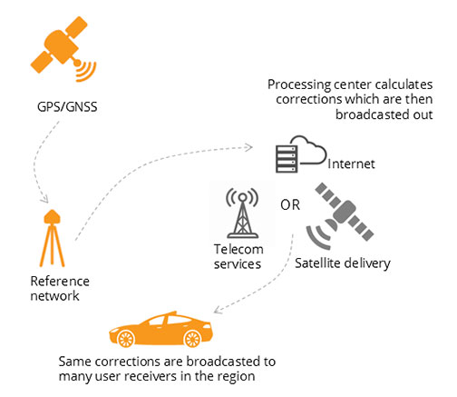
Use of a reference station, also known as a base station, can overcome both satellite and atmospheric errors.
A reference station is a GNSS receiver which installs at a fixed and precisely known location. It estimates GNSS errors and sends them in the form of GNSS corrections to the user receiver (see image below). A reference network consists of interconnected reference receivers spread over an area.
A user receiver gets data, which it uses to correct satellite and atmospheric errors.
Robust receiver technology and careful operation can partially handle receiver-side errors. Depending on the type of corrections applied, it can take a few seconds to several minutes initialization time until high accuracy is achieved.
Types of corrections
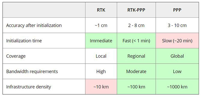
Until recently, RTK and PPP were the established methods of providing GNSS corrections to user receivers.
Nowadays, the demand for high accuracy positioning is on the rise, paving the way for new positioning techniques such as the hybrid PPP-RTK.
RTK – the highest level of accuracy
In the Real Time Kinematic (RTK) method, a user receiver gets correction data from a single base station or from a local reference network. It then uses this data to eliminate most of the GNSS errors.
RTK is based on the principle that the base station and the user receiver are located close together (maximum 40 km or 25 miles apart) and therefore “see” the same errors.
For example, since the ionospheric delays are similar for both the user and the reference station, they can be cancelled out of the solution, allowing higher accuracy.
In the RTK method corrections are provided for a specific location.
In the PPP and PPP-RTK methods, they broadcast a correction model to a larger area but with slightly lower accuracy.
To transmit this correction model, they use a message format called Space State Representation (SSR). There is some confusion in the industry about the term “SSR”. It is occasionally a buzzword referring to traditional PPP services, as well.
PPP – globally accessible and accurate, but at a cost
The Precise Point Positioning (PPP) corrections contain only the satellite clock and orbit errors.
Since these errors are satellite specific, and thus independent of the user’s location, only a limited number of reference stations around the world are needed.
This method produces lower accuracy levels because it does not include atmospheric errors. Plus, it takes up to 20-30 minutes to initialize; which may not be practical for some applications.
Traditionally, the maritime industry uses PPP. Today, it expanded to various land applications such as agriculture, as a convenient way to get global GNSS corrections.
PPP-RTK, the best of both worlds?
PPP-RTK (a.k.a. SSR) is the latest generation of GNSS correction services. It combines near-RTK accuracy and quick initialization times with the broadcast nature of PPP.
A reference network, with stations about every 150 km (100 miles), collects GNSS data and calculates both satellite and atmospheric correction models.
As explained, atmospheric corrections are regional. Thus, it requires a denser reference network than for PPP. These corrections are broadcast to subscribers in the area via Internet, satellite or telecom services.
Subscribed receivers use the broadcasted correction model to deduce their location-specific corrections, resulting in sub-decimeter accuracy.
Comparing the three GNSS correction methods
The table below compares the three correction methods, highlighting their strengths and weaknesses.
The infrastructure density and initialization time for all three methods vary with the different kinds of errors that are corrected, see image below.
The broadcast nature of PPP-RTK and PPP, as well as the lighter infrastructure that they require, makes these methods scalable for mass market applications.
Types of errors which are corrected by each of the three methods.
Some GNSS receivers also incorporate advanced positioning algorithms to compensate for receiver-side issues such as multipath, jamming and spoofing. This adds reliability and robustness to high accuracy positioning.
Getting GNSS Corrections
Modern industrial receivers often get their GNSS corrections via a subscription service. These corrections are delivered via Internet (using NTRIP protocol), satellite or 4G/5G.
Today, driven by the high accuracy demands of the automotive industry, automation and smart devices, there is a boom in the correction service market.
Automotive suppliers and many other new players are deploying infrastructure to set up services for centimeter-level positioning around the globe.
User receivers often get their GNSS corrections via a subscription service delivered via internet, satellite or 4G/5G.
PPP and PPP-RTK corrections can even transmit directly by the GNSS satellites, as in the Japanese CLAS service from the QZSS constellation, or in the planned High-Accuracy Service (HAS) from Galileo.
Depending on the network density and quality of the error modelling, different initialization times and accuracies can be achieved. This means that positioning quality can vary from one service provider to another.
Major telecom companies such as Deutsche Telekom as well as the Japanese Softbank and NTT are equipping their infrastructure with GNSS receivers to enable new corrections services.
3GPP, which provides specifications for mobile telephony including LTE, 4G and 5G, now covers broadcasting of GNSS satellite corrections in their mobile protocol.
Since reference receivers are becoming part of critical infrastructure, such as telecom towers, it is essential that they have a high level of security to protect them from potential jamming or spoofing attacks.
Which corrections are right for me?
The right correction service for your technology depends on your location and service area, your accuracy and reliability needs, as well as budget.
Because the corrections market keeps expanding, it is now more important than ever that integrators or GNSS manufacturers assist you in selecting the best correction method for your industrial application.
If you choose a GNSS receiver which does not “lock” you to a certain correction service, you are free to choose a correction method which is most suitable for your application and its location. Such “non-locking” open-interface receivers also offer customers flexibility to switch to another more beneficial service in the future, as correction methods keep evolving.
Footnote:
[1] Global Navigation Satellite System including the American GPS, European Galileo, Russian GLONASS, and Chinese BeiDou, Japan’s QZSS and India’s NavIC. These satellite constellations broadcast positioning information to receivers which use it to calculate their location.
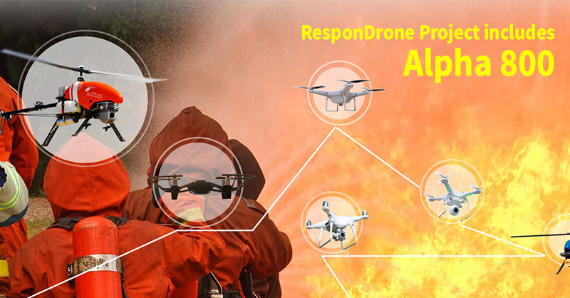
ResponDrone Project includes Alpha 800 UAV in its multiple-drone deployments. Alpha Unmanned Systems’ Alpha 800 helicopter UAV now supports the ResponDrone project. The Alpha 800 provides situational awareness for first responders.
The ResponDrone project is an initiative co-funded by the European Union (EU) and Korean government. Its mission is to provide critical information and communication services in emergency situations.
Situational Challenges
During disaster situations, lack of line of sight and deficiencies in communications make it difficult for first responders to execute missions.
Plus, time is often a critical factor. This adds another dimension of difficulty for emergency response teams.
Thus, rapid data collection is vital during the early stages of a disaster.
UAVs, especially rotary-wing platforms, are becoming a leading tool for first responders. Unmanned vehicles provide an initial means of communication. In addition, they help gather data for status reports and situational analysis.
ResponDrone Project
Systems like ResponDrone, deploy several UAVs concurrently.
As such, they can amass information about possible access routes and victim locations. This helps provide precision mapping to designate evacuation and supply routes, take-off and landing areas.
This information facilitates faster and easier on-scene arrival capabilities.
Plus, drones allow teams to make real-time decisions and anticipate potential situational changes.
Pilots work from a safe position and provide rapid feedback to decision-makers, who can act quickly on the data collected.
Alpha 800 UAV
The Alpha 800 UAV is a rotary-wing aircraft capable of flying at low speed and low altitude. It requires only a 9m2 area for its VTOL (vertical take-off and landing) operation.
It can operate in maritime environments and in temperature ranges of -10ºC to +50ºC. This makes it a flexible solution that deploys under a wide range of conditions.
With a 3kg payload capacity, it can equip with thermal, night vision, LiDAR, IR, or mobile phone seeker sensors.
Other features of the Alpha 800 that make it highly suited to emergency and disaster response applications, include:
Hover flight mode. Useful when communications are lost or when terrain hinders or blocks signal access. In such situations, the Alpha 800 can serve as communications relay or as a source of real-time video, data and photography.
VTOL operation in a small space. Enables emergency services to drop and pick up supplies in minimal time with maximum safety and precision.
Quick deploy. Deploys within 10-minutes and is small enough to transport using only a car or pick-up van.
Budget friendly. Lower maintenance, operational and crew costs when compared to conventional manned helicopters.
Alpha Security and Defence is a division of Alpha Unmanned Systems.
When compared to conventional imaging -- such as a color camera -- hyperspectral imaging yields more accurate color and material identification. It does this by providing far more detailed information for each pixel.
A color camera offers only three channels. In contrast, a hyperspectral camera divides the light signal into many tens to hundreds of bands or channels. This additional resolution improves machine vision accuracy, often dramatically.
Technology extended
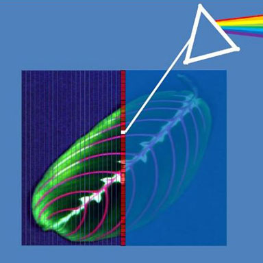
Hyperspectral imaging is really a logical extension of conventional spectroscopy.
A spectrometer spreads a light beam into a continuous band of “colors.” For example, think of a prism. Taken together, the bands of colors are a spectrum of the light beam. Spectroscopy is the study or use of light spectra.
A hyperspectral imager acts like hundreds of spectrometers in parallel. This provides a spectral curve for each pixel in a scene (indicated schematically below).
A hyperspectral imager spreads the light from every pixel of an image into a continuous spectrum. It provides detailed information to accurately identify or classify objects in the scene.
Why is it useful?
In contrast to the human eye, which captures only three primary colors, computer vision systems utilize many more color channels.
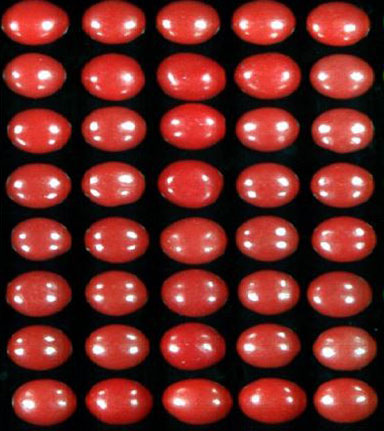
As an example, consider the color image of two types of candy shown below.
Color image of two types of candy. One is organized into the shape of an "I" in the center.
The position of one type of candy is in the shape of an “I.” A conventional color imaging system would have great difficulty discriminating between the two similarly colored candy types (as do many humans).
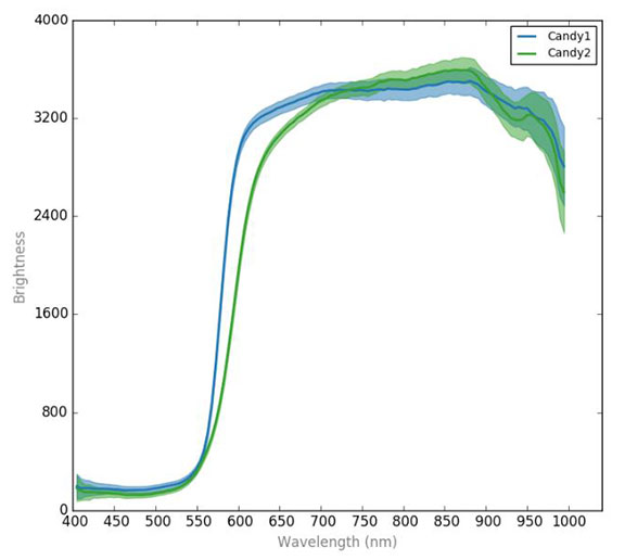
Show below are spectral curves for the two types of candy.
Spectral curves of the two candy types shown in previous picture. The dark blue and green lines indicate the average and the shaded regions indicate the standard deviation. Notice the curves overlap for much of the spectral range but deviate between 550 nm and 600 nm in Wavelength.
As one would expect with similarly colored objects, there is considerable overlap in the curves. However, there is also a region where there is a clear difference.
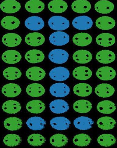
Machine learning algorithms readily exploit the difference in the spectral curves. The difference helps accurately classify the candy types -- shown in a false color classification map. The false colors match the color of the curves.
Classification map of the colored candies.
Hyperspectral data accurately differentiates the candy types. The classification is performed pixel-by-pixel. Note, almost every non-glare pixel is correctly classified.
Hyperspectral difference
Hyperspectral imaging provided more information per pixel. This information helps distinguishing between similarly colored objects or materials.
Users can interface outputs to robots, air-jets, labeling devices, etc.
Much like the human eye, hyperspectral imaging can apply to a wide range of applications. Such applications include: quality control (lumber, textiles, paper, building materials, drugs), process control (thin films, moisture content, color), sorting (food, recyclable materials, minerals), remote sensing (ocean color, environmental monitoring, agriculture), and more.
Today, hyperspectral technology is on platforms ranging from microscopes to airplanes -- including UAVs.
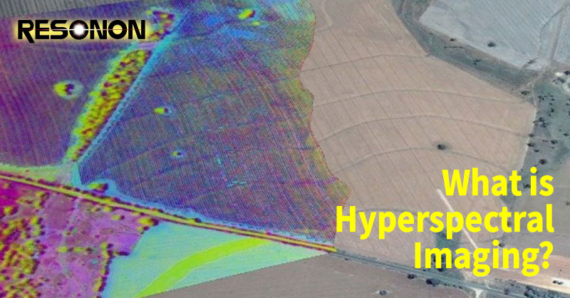
Resonon offers a line of compact, low-cost, rugged hyperspectral imaging systems. The Pika-L, for example, integrates on to many UAV platforms.
The Inertial Sense µINS is a miniature, GNSS aided Inertial Navigation System (GNSS-INS) module. It includes all the functionality of the µAHRS and provides orientation, velocity, and position.
Users can apply RTK Base station correction data to achieve CM level precision. Sensor data from MEMs gyros, accelerometers, magnetometers, barometric pressure, and GNSS fuse for an optimal estimation.
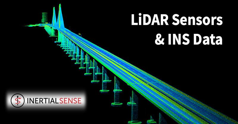
Livox LiDAR
Currently, Livox sensor's are in use for automotive, robotics and surveying 3D Mapping Applications.
Livox offers a line of advanced sensor units. As such, companies and developers have a reliable route to incorporate this technology into survey projects and autonomous vehicle platforms.
Livox sensors’ performance, affordability, and reliability enable it for use in autonomous driving, robotics and UAV surveying and mapping.
Livox MID-40 LiDAR sensor and Inertial Sensor INS are in use in harsh environments where there are vibrations from the aerial craft. Vibrations often create big problems for most Inertial Measurement Units.
LiDAR Sensors and INS Data
INS and GNSS are necessary to compensate for LiDAR movement -- both rotation and translation -- during drone flight.
As the UAS flies, motion is inevitable due to air turbulence, propeller motion and other external and internal forces.
By incorporating data from an INS, it is possible to measure all LiDAR movements. This includes vibration which is required for sensor fusion and mapping.
Flying with the companion INS separates the payload from the drone. Plus, it allows Livox customers the flexibility to choose any drone platform.
To keep the cost of the survey application down, Livox integrated the tight angular accuracy INS sensors from Inertial Sense.
By using an external INS from Inertial Sense, Livox combined and synced data.
To achieve the finest detail aerial mapping, the rotation and translation measured by the INS sensor and matched to the LiDAR data needed to be accurate to the centimeter.
Development and Integration
To start the development and integration, Livox selected the µINS development kit.
The development kits include the selected module, antennas and appropriate cables to connect to the system. Plus, it includes technical support for system integration.
Main technical characteristics: up to 1KHz IMU, 500Hz INS Update Rate; measurement range of angular resolution 0.1 degrees roll/pitch, GNSS update rate is 5Hz, power voltage 3.3 V; overall dimensions: 35.9 x 25.4 x 11.2mm, weight 10.5g.
Improved Accuracy
The end result was impressive.
Livox LiDARs paired with Inertial Sensor’s miniature, low-cost, GNSS aided Inertial Navigation System (GNSS-INS) module made aerial mapping more efficient and affordable than ever.
INS advanced algorithms provided output from MEMs inertial sensors, magnetometers, barometric pressure, and high-sensitivity GNSS receivers with centimeter accuracy to obtain fast, accurate, and reliable attitude, velocity, and position data during aerial mapping.
With accurate INS data (position and pose) from the sensors, Livox improved final data point accuracy.
Livox projected all data points to an Earth frame to build a global map. As a result, the team accurately mapped the entire 3km-long Huizhou Bay Bridge, located in Guangdong, China...down to its finest details.
Today, the INS line is in wide use in many applications.
Plus, it has proven its outstanding reliability and accuracy in challenging conditions -- high vibration, extreme temperatures, and tough mission profiles.
With integration complete, the INS is fully compatible and ready for autonomous unmanned flight system applications.
Tactical Grade IMU
The IMU component is tactical grade.
It is reliable for tactical guidance, navigation, flight control, stabilization, pointing systems, and other applications.
With Angular Rates and Accelerations data transfer rate reaching up to 2000 Hz rate, the low power consuming IMU provides an excellent SWAP-C advantage over legacy IMUs based off tactical grade fiber-optic gyros (FOG).
Plus, the on-board GNSS receiver is fully configurable to reach real-time position accuracy on one centimeter.
Veronte Autopilot
The Veronte Autopilot by by Embention features many top-of-the-line options which distinguish it in the marketplace.
Such features include: extended efforts for line of sight (LOS) and beyond line of sight (BLOS) communication, intuitive and high-performing software, and a configurable navigation solution for various applications - it is fast becoming a customer favorite.
Additionally, with the navigational accuracy provided by the INS-P, the autopilot offers highly accurate navigation in a GNSS-denied environment.
Plus, it is compatible with mission critical items such as tracker antennas, flight simulators and camera payloads.
This platform solution can customize to fit the needs of the end user.
About Inertial Labs, Inc.
Established in 2001, Inertial Labs is a leader in position and orientation technologies for both commercial/industrial and aerospace/defense applications.
About Embention
Founded in 2007, Embention develops components and critical systems for UAS.