Autopilots and advanced GNSS use types is an important piece to a UAVs functionality.
Obtaining the most accurate information about a UAV's position and attitude -- anywhere in the world and in all weather conditions -- is fundamental.
Therefore, understanding the types and functions of advanced GNSS systems is essential.
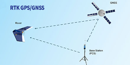
RTK GPS/GNSS Positioning
In Real-Time Kinematic (RTK) mode the UAV calculates its position in relation to the Base position location (GCS). In turn, the base station sends corrections to the GPS/GNSS air module.
This process improves the relative accuracy between both devices; eliminating errors introduced by the atmosphere and other factors.
With RTK positioning activated the relative accuracy improves to the centimetre scale.
Depending on operational needs, operators can activate RTK positioning for the flight duration. Or, operators can automate the function so the drone receives RTK corrections during critical flight phase.
The landing phase is an example. RTK corrections ensure centimetre accuracy at touchpoint time (fixed-wings), landing on an exact point (multi-rotor) or activate in advanced modes (landing on a network or moving vehicle).
One drone application that takes advantage of RTK mode is photogrammetry.
Photogrammetry with drones makes possible to model a 3D surface, create plans and perform measurements. As such, achieving high accuracy is vital.
Drone camera positions with RTK calculate in real-time. This allows correcting camera positions of a few precision centimetres, both vertically and horizontally.
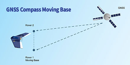
GNSS Compass Moving Base
With this method, a moving vehicles attitude and orientation is estimated without the use of a magnetometer or other sensors sensitive to electromagnetic interference.
For this, a minimum of two GNSS antennas (GPS, Glonass & BeiDou) provide a known relative position between them.
The reference station and mobile receivers can move while calculating a precise vector between the receiver antennas. They calculate the position and the attitude of the vehicle based on the GNSS signal.
Helicopters frequently use this model in order to achieve magnetometer redundancy.
An example of loss orientation is in the vicinity of high voltage towers. Since the electromagnetic interference presence interferes with the magnetometers measurement.
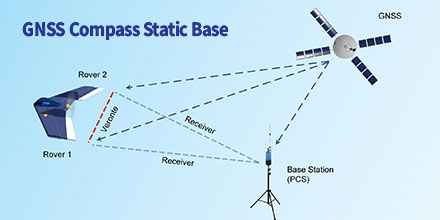
GNSS Compass Static Base
In this model, a fixed base station provides the corrections for the platform orientation.
Plus, the UAV's avionics system can use previously measured coordinates of the antenna position at the base. This guarantees a better absolute drone position.
Knowing the two vectors between the base and each UAV antennas, the avionic system calculates the vector between the two air antennas.
Uses include landing on mobile platforms such as ships.
As such, the accuracy of the mobile platform is much greater when communicating orientation corrections through the fixed base.
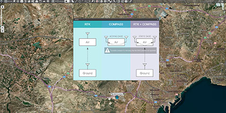
GNSS Use in Veronte Autopilot
Veronte Autopilot incorporates all these types of GNSS use without the need to integrate any additional hardware.
A double GNSS sensor (GPS, Glonass & BeiDou) -- on the ground and in the air -- can activate from Veronte PIPE software. The activation is done in a simple way with the wizard created for the different scenarios.
At Embention, our team of Engineers continuously incorporate the latest technology into our autopilots.
Veronte Autopilot features a navigation system that -- regardless of location and weather -- provides high accuracy information about the position and attitude of the drone.
Delivering high accuracy with GNSS, is it possible? Let’s say you need reliable accurate global positioning in your technology. You do some research and decide a multi-frequency GPS/GNSS[1] receiver is the solution. So, you order an evaluation kit.
Now, how do you get your receiver to deliver the high accuracy that it promises?
GNSS receivers rely on external corrections to compensate for various imperfections called GNSS errors to achieve decimeter or even centimeter level accuracy as fast as possible.
Correcting GNSS errors
GNSS based positioning is calculated using a method which, by itself, is limited in accuracy. The accuracy limitations are due to several errors caused by GNSS satellites as well as the Earth’s atmosphere.
GNSS satellites are essentially highly accurate synchronized clocks orbiting the Earth. These satellites constantly broadcast their positioning and timing information.
A GNSS user receiver gets signals from several of these “flying clocks” and calculates its distance to each satellite. When the receiver knows the distance to at least four satellites it can deduce its own position.
However, certain errors affect the accuracy of this position.
Even advanced clocks on board GNSS satellites experience minute drifts which cause clock errors.
As GNSS satellites orbit the Earth, their movement along the path is predictable. However, these predictions are not ideal, which results in what’s called orbit errors.
Plus, satellite equipment also introduces small signal errors. They model these errors as satellite biases.
Atmospheric errors
Additionally, there are atmospheric errors. As the signal passes through the Earth's ionosphere (outer layer) and troposphere (layer near the Earth's surface), it experiences distortions and delays.
Finally, the local environment around the receiver as well as the receiver itself can introduce errors. For example, satellite signals can reflect off buildings and tall structures, a phenomenon referred to as multipath.
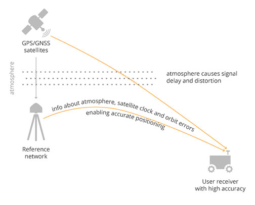
A GNSS receiver cannot correct satellite and atmospheric errors by itself. It relies on data provided by an external source for these corrections.
Clock and orbit errors are satellite dependent, which means that they are the same around the world.
On the other hand, atmospheric errors depend on the path the signal takes as it travels from the satellites to the user. Therefore, they differ depending on the receiver’s location.
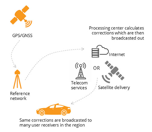
Use of a reference station, also known as a base station, can overcome both satellite and atmospheric errors.
A reference station is a GNSS receiver which installs at a fixed and precisely known location. It estimates GNSS errors and sends them in the form of GNSS corrections to the user receiver (see image below). A reference network consists of interconnected reference receivers spread over an area.
A user receiver gets data, which it uses to correct satellite and atmospheric errors.
Robust receiver technology and careful operation can partially handle receiver-side errors. Depending on the type of corrections applied, it can take a few seconds to several minutes initialization time until high accuracy is achieved.
Types of corrections
Until recently, RTK and PPP were the established methods of providing GNSS corrections to user receivers.
Nowadays, the demand for high accuracy positioning is on the rise, paving the way for new positioning techniques such as the hybrid PPP-RTK.
RTK – the highest level of accuracy
In the Real Time Kinematic (RTK) method, a user receiver gets correction data from a single base station or from a local reference network. It then uses this data to eliminate most of the GNSS errors.
RTK is based on the principle that the base station and the user receiver are located close together (maximum 40 km or 25 miles apart) and therefore “see” the same errors.
For example, since the ionospheric delays are similar for both the user and the reference station, they can be cancelled out of the solution, allowing higher accuracy.
In the RTK method corrections are provided for a specific location.
In the PPP and PPP-RTK methods, they broadcast a correction model to a larger area but with slightly lower accuracy.
To transmit this correction model, they use a message format called Space State Representation (SSR). There is some confusion in the industry about the term “SSR”. It is occasionally a buzzword referring to traditional PPP services, as well.
PPP – globally accessible and accurate, but at a cost
The Precise Point Positioning (PPP) corrections contain only the satellite clock and orbit errors.
Since these errors are satellite specific, and thus independent of the user’s location, only a limited number of reference stations around the world are needed.
This method produces lower accuracy levels because it does not include atmospheric errors. Plus, it takes up to 20-30 minutes to initialize; which may not be practical for some applications.
Traditionally, the maritime industry uses PPP. Today, it expanded to various land applications such as agriculture, as a convenient way to get global GNSS corrections.
PPP-RTK, the best of both worlds?
PPP-RTK (a.k.a. SSR) is the latest generation of GNSS correction services. It combines near-RTK accuracy and quick initialization times with the broadcast nature of PPP.
A reference network, with stations about every 150 km (100 miles), collects GNSS data and calculates both satellite and atmospheric correction models.
As explained, atmospheric corrections are regional. Thus, it requires a denser reference network than for PPP. These corrections are broadcast to subscribers in the area via Internet, satellite or telecom services.
Subscribed receivers use the broadcasted correction model to deduce their location-specific corrections, resulting in sub-decimeter accuracy.
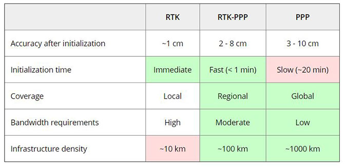
Comparing the three GNSS correction methods
The table below compares the three correction methods, highlighting their strengths and weaknesses.
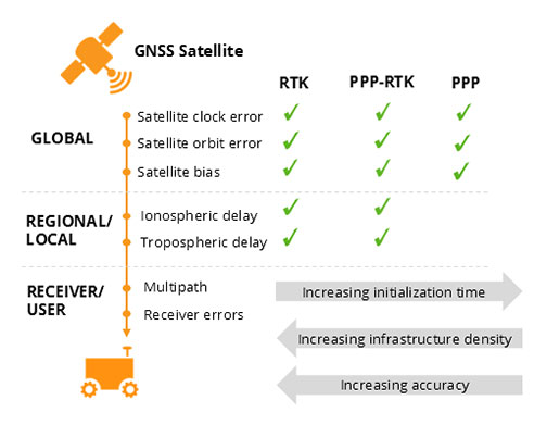
The infrastructure density and initialization time for all three methods vary with the different kinds of errors that are corrected, see image below.
The broadcast nature of PPP-RTK and PPP, as well as the lighter infrastructure that they require, makes these methods scalable for mass market applications.
Types of errors which are corrected by each of the three methods.
Some GNSS receivers also incorporate advanced positioning algorithms to compensate for receiver-side issues such as multipath, jamming and spoofing. This adds reliability and robustness to high accuracy positioning.
Getting GNSS Corrections
Modern industrial receivers often get their GNSS corrections via a subscription service. These corrections are delivered via Internet (using NTRIP protocol), satellite or 4G/5G.
Today, driven by the high accuracy demands of the automotive industry, automation and smart devices, there is a boom in the correction service market.
Automotive suppliers and many other new players are deploying infrastructure to set up services for centimeter-level positioning around the globe.
User receivers often get their GNSS corrections via a subscription service delivered via internet, satellite or 4G/5G.
PPP and PPP-RTK corrections can even transmit directly by the GNSS satellites, as in the Japanese CLAS service from the QZSS constellation, or in the planned High-Accuracy Service (HAS) from Galileo.
Depending on the network density and quality of the error modelling, different initialization times and accuracies can be achieved. This means that positioning quality can vary from one service provider to another.
Major telecom companies such as Deutsche Telekom as well as the Japanese Softbank and NTT are equipping their infrastructure with GNSS receivers to enable new corrections services.
3GPP, which provides specifications for mobile telephony including LTE, 4G and 5G, now covers broadcasting of GNSS satellite corrections in their mobile protocol.
Since reference receivers are becoming part of critical infrastructure, such as telecom towers, it is essential that they have a high level of security to protect them from potential jamming or spoofing attacks.
Which corrections are right for me?
The right correction service for your technology depends on your location and service area, your accuracy and reliability needs, as well as budget.
Because the corrections market keeps expanding, it is now more important than ever that integrators or GNSS manufacturers assist you in selecting the best correction method for your industrial application.
If you choose a GNSS receiver which does not “lock” you to a certain correction service, you are free to choose a correction method which is most suitable for your application and its location. Such “non-locking” open-interface receivers also offer customers flexibility to switch to another more beneficial service in the future, as correction methods keep evolving.
Footnote:
[1] Global Navigation Satellite System including the American GPS, European Galileo, Russian GLONASS, and Chinese BeiDou, Japan’s QZSS and India’s NavIC. These satellite constellations broadcast positioning information to receivers which use it to calculate their location.
Knowing the correct time is something we take for granted. But, who exactly decides the correct time in the first place? How does anyone go about determining the correct time? And, how does GPS fit in to the story?
To determine the time, BIPM in Paris relies on contributions from a worldwide collaboration of timing laboratories. Each of these laboratories maintain their own measure of time and compare it with GPS time.
One clock to rule them all
Timing labs employ precise clocks. To measure time precisely, Cesium atomic clocks and Hydrogen masers are among the most popular devices.
Although these clocks are very reliable -- accurate to about 2 nanoseconds per day -- small variations still occur. At BIPM in Paris, they compare the performance of clocks in timing labs from around the world. They use a weighted average of all contributions and calculate Coordinated Universal Time (UTC).
Interestingly, labs with better performing or more stable clocks receive more weight in the UTC calculation.
This means that real-time UTC is only an approximation... albeit a very accurate one. Thus, they determine the more precise calculation in retrospect.
The Circular-T journal, published monthly by BIPM, contains the small corrections. They apply these corrections to UTC for the previous month.
GPS receivers and time
Each timing lab contributing to UTC measures its own version of UTC. For example, UTCBrussels is the Belgian measure of UTC.
So how does BIPM compare the performance of all these different clocks?
It uses GPS receivers. Or, more accurately, GNSS (Global Navigation Satellite System) receivers which - in addition to GPS -- track constellations, such as: GLONASS, Galileo, BeiDou and IRNSS.
The precise measurement of time is at the heart of every GPS receiver.
They determine the distances between satellite and receiver, used to calculate position, by measuring the transit times of the satellite signals to the receiver.
An error of 1 nanosecond in the transit time translates into an error of 30cm in the distance.
Flying clocks
The GPS satellite constellation uses its own precise measure of time called: GPS time. Each GPS satellite has its own, on-board set of atomic clocks. Thus, satellites are also very accurate flying clocks.
By tracking a GPS satellite, a receiver can record the time differences between its own receiver clock and the satellite clock, e.g. UTCBrussels - GPS time.
The time differences, along with other information, are in a data format called CGGTTS and sent to BIPM. Using CGGTTS and other data, BIPM compares a clock in Brussels with a clock in New York by subtracting the individual differences with GPS time. As such, this technique is known as "common view".
UTCBrussels - UTCNew York = (UTCBrussels - GPS time) - (UTCNew York - GPS time).
The two GPS time terms above cancel each other out leaving the difference between UTCBrussels and UTCNew York.
Setting up a timing laboratory
In order to compare the atomic clocks used in timing labs around the world, they need to connect to a GPS timing receiver. A GPS timing receiver uses an external atomic clock instead of its own clock; which it does by using two output signals from the atomic clock:
a pulse every second synchronised to UTC (PPS IN) and
a 10 MHz frequency reference that is essentially a sine wave (REF IN)
Figure 3 depicts the basic ingredients of a timing laboratory.
However, to reach the nanosecond accuracy required, it takes a great deal of expertise and preparation.
Signal delays in all elements in the setup require accurate calibration. To do this, BIPM maintains a set of pre-calibrated travelling receivers as calibration references.
As well as providing 1/3 of the timing receivers used for the calculation of UTC, Septentrio also provides BIPM with timing receivers for calibration.
Pushing the boundaries of science
Beyond defining and disseminating UTC, GPS timing receivers are staking their place at the forefront of science.
For example, take the case of the T2K experiment. By precisely measuring the transit time of neutrinos between two locations, limits are placed on their mass. Thus, it sheds more light on the nature of these elusive particles.
At the other end of the size spectrum, the Very-Long-Baseline Interferometry (VLBI) technique uses radio telescopes at distant locations. These telescopes are linked together in networks by time-synching their observations using GPS common view. The resulting resolution is far in excess of anything that can be achieved by any single telescope on its own.
GPS technology continues to find new ways to improve our world and advance our knowledge of it.
Affordable, high-end drones coupled with easy-to-use mission-planning tools, created the perfect environment for drones to flourish.
No longer the preserve of specialists, applications using drones have ventured into survey, inspection and volume analysis.
The impact of drones is little short of revolutionary.
But, in the air, the stakes are higher. When things go wrong, the consequences are invariably much more serious than for a ground-based application. One of the biggest threats to drone safety is GNSS interference.
At the very least, disruptions to satellite signals can degrade position quality. When this occurs it causes fall-backs from high-precision RTK and PPP modes to less-precise modes. In the most extreme cases, interference can result in complete loss of signal tracking and positioning.
Self interference
Other components installed on a UAV is often a significant source of interference. The restricted space often means that the GNSS antenna is in close proximity to other electrical and electronic systems.
Figure 1 shows what happened to the GPS L1-band spectrum when a GoPro camera was installed on a quadcopter close to the GNSS antenna without sufficient shielding. The three peaks are exactly 24 MHz apart. This points to their being harmonics of a 24 MHz signal: the typical frequency for a MMC/SD logging interface.
An AsteRx4 receiver, which includes the AIM+ system, was selected for this setup. As well as mitigating the effects of interference, AIM+ includes a spectrum plot to view the RF input from the antenna in both time and frequency domains.
At the installation stage, the ability to view the RF spectrum is an invaluable tool for identifying the source of interference. Plus, it helps with determining the effectiveness of measures such as modifying the setup or adding shielding.
For the quadcopter installation in this example, the loss of RTK was readily diagnosed. The problem was solved by placing the camera in a shielded case. All this while the quadcopter was still in the workshop.
External sources of interference
GNSS receivers on-board UAVs can be particularly vulnerable to external sources of interference, be they intentional or not. In the sky, the signals from jammers can propagate over far longer distances than they would on land.
In the case of UAV inspections of wind turbines for example, many countries encourage the construction of windmills next to roads. However, this situation increases the chance of interference from in-car chirp jammers.
Though illegal, chirp devices are cheap and readily available on the internet. For example, an individual using a chirp jammer can drive around undetected by the GPS trackers on the vehicle. Car thieves can disable GPS anti-theft devices on stolen vehicles with chirp jammers.
External interference: the effect of a chirp jammer on a UAV flight
Although transmitting with a power of around 10 mW, chirp jammers are powerful enough to knock out GNSS signals in a radius of several hundred meters on land. In the air, unhindered by trees, building or other obstacles, these jamming signals have a far greater reach. Thus, the UAV is much more vulnerable to interference.
Figure 2 shows how a 10mW chirp jammer can knock out RTK positioning over more than 1 km in a high-end receiver.
Even a low-end consumer-grade L1 receiver, being less accurate and thus less sensitive, loses stand-alone positioning over several hundred meters.
With AIM+ activated, the AsteRx4 is able to maintain an RTK fix throughout the simulated flight. It also shows no degradation to its position variance.
Solving chip-jammer interference on UAV systems
A comprehensive approach puts interference considerations at the forefront of receiver design and incorporates it into every stage of signal processing. In the case of the AsteRx4 and AsteRx-m2, the antenna signal is immediately digitized after analogue filtering and automatically cleansed of interference using multiple adaptive filtering stages.
As each interfering signal has its own individual footprint, the ability to visualize the RF signal in both time and frequency domains allows drone users to identify sources of self-jamming and adapt their designs accordingly before the drone gets in the air.
When it is in the air, AIM+ is able to mitigate jamming from external sources: a set of configurable notch filters are complemented by an adaptive wide-band filter capable of rejecting more complex types of interference such as that from chirp jammers, frequency-hopping signals from DME/TACAN devices as well as high-powered Inmarsat transmitters.
You can shop Septentrio's line of solutions at Unmanned Systems Source.
February 13, 2017 - Septentrio GNSS technology continues to provide solutions for challenging situations.
Case in point? The Belgian dredging, environmental and engineering group DEME. They rely on the accuracy and reliability of the AsteRx family of precise GNSS positioning solutions from Septentrio.
DEME is using Septentrio’s AsteRx GNSS receivers to obtain centimeter-level accuracy for all their dredging and marine construction operations worldwide.
These receivers are designed to operate in difficult conditions. From ice-covered Arctic ports to the tropical climates of Southeast Asia; whether dredging a few meters from the coast line to constructing wind turbines kilometers out at sea.
Septentrio GNSS technology, a case study
DEME began using Septentrio’s solutions over 10 years ago. While dredging in the Belgian town of Oostende, DEME couldn't obtain a reliable RTK position from their GNSS equipment. The problem? Interfering radio signals from a local radio tower. Septentrio worked with DEME to identify the source of the interference. Once the problem was discovered they modified a standard RTK receiver with special firmware to address the jamming problem.
This case, along with others faced by Septentrio's customers in the field, began development of a dedicated interference mitigation technology called AIM+ which is now standard in Septentrio’s GNSS solutions.
History of success
Septentrio’s AsteRx GNSS receivers are deployed on DEME’s ships around the world. They have been vital to DEME for the success of projects such as the creation of Gateway Port in London, UK; the construction of Deurganckdock, Antwerp, Belgium; the
Pearl Qatar City; Thornton Bank Offshore Windfarm, Belgium, extension of the Suez Canal, Egypt and many more.
“’Creating land for the future’ is the slogan here at DEME and this is thanks in part to the accuracy and robustness of the solutions offered by Septentrio” stated Lorentz Lievens, Head of Survey Department.
“Jamming is a concern which DEME has seen more and more all over the world. Septentrio’s receivers are unique in that they continue to provide an accurate solution even in areas of high radio and ionospheric interference allowing DEME to deliver projects on time and on budget," continued Lievens.
Septentrio’s precise positioning solutions will remain vital for DEME to deliver quality and cost-effective operations around the world for many years to come.”
About Septentrio
Septentrio designs, manufactures and sells high-precision multi-frequency multi-constellation GPS/GNSS equipment, which is used in demanding applications in a variety of industries such as marine, construction, agriculture, survey and mapping, geographic information systems (GIS), and unmanned aerial vehicles (UAVs) as well as other industries. Their receivers deliver consistently accurate GNSS positions scalable to centimetre-level, and perform solidly even under heavy scintillation or jamming. Receivers are available as OEM boards, housed receivers and smart antennas.
Unmanned Systems Source is pleased to partner with Septentrio. Shop Septentrio's product lineto find the solution that is right for your application.
Your challenge, should you choose to accept it…
You’ve been asked to survey some points on the ground with centimeter-level accuracy. Feeling confident?
How about a few hundred points spread over 7.5 hectares (18.53 acres) and the job has to be done in one afternoon. Throw in the fact that the area you have to survey is in a quarry which has been closed off due to a recent landslide. Still feeling confident?
You should and here’s why.
Improvements in Unmanned Aerial Vehicle (UAV) technology combined with more compact high-end Global Navigation Satellite Systems (GNSS) receivers means that you no longer have to compromise on precision to measure in those hard-to-reach areas.
Before the flight
UAVs have become more reliable and easier to work with: from programming flight paths to installing additional equipment on board, UAV applications are no longer confined to a limited group of specialists.
For a survey flight, your UAV will need to have installed: a high-resolution camera and a high-end GNSS receiver module. To fly the UAV through a pre-programmed flight plan, an autopilot flight controller is often included.
The flight
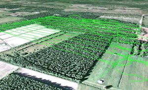
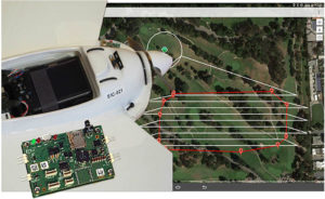
The flight path shown below covered 7.5 hectares (18.53 acres) and was flown in 15 minutes. The 143 photographs taken during the flight were geotagged with GNSS standalone mode positions. Accuracies in standalone mode are typically around 1 to 4 meters (3.28 to 13.13 ft).
If the on-board receiver receives correction information in real time from a nearby GNSS base station, it calculates positions using the more precise (centimeter-level) RTK mode.
With the necessary data from a GNSS base station, RTK positioning can also be calculated ‘offline’ in the processing step using GeoTagZ as described below. Offline reprocessing using GeoTagZ removes the need for a real-time data connection between the UAV and base station which simplifies the hardware setup on the UAV and reduces the payload.
Back in the office: Geotagging
The AsteRx-m UAS receiver recorded the times the photographs were taken by time-stamping a pulse signal from the camera shutter. It also recorded dual-frequency GNSS measurements during the flight.
The GeoTagZ software uses the GNSS data recorded by the receiver and, combining it with the base station reference file, is able to calculate centimeter-level RTK positions for georeferencing the photographs. The EXIF data of the photographs is then replaced with the more accurate RTK georeferences ready for image processing.
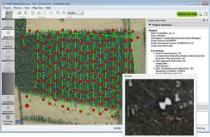
In this example, GeoTagZ was able to match images with shutter events despite the receiver file covering a longer time period and so having more events than images.
With the photographs now stamped with a precise time and location, they can be processed. The blue crosses in the screenshot below are the ground locations of check points used to determine the final precision and accuracy. They play no part in the processing.
This example details the use of Pix4D and PhotoScan however, other similar image processing tools could equally well have been used.
What accuracy can you expect on the ground?
The photographs in this example were processed using two popular image processing software tools Pix4D and PhotoScan from Agisoft. The values highlighted below are the 3D-RMS values from their respective reports. These values are calculated from the sum of squared differences between each of the 20 check points’ surveyed positions and their positions as calculated using the image processing software.
The 3D accuracies for both software tools are better than 3.5 cm, with the height (Z) being the largest contributor to the total error. This is the same accuracy that a human surveyor would typically reach when surveying each of the 20 points check points manually.
Pix4D
Agisoft PhotoScan
GeoTagZ provides the missing link to centimeter-level ground mapping
The combination of high-resolution aerial photographs with GeoTagZ, for georeferencing with RTK positions from a compact high-end receiver module, provides the complete input for centimeter-level mapping precision on the ground. The same precision as manual survey can thus be achieved in a fraction of the time for all ground points within the surveyed area.


 Affordable, high-end drones coupled with easy-to-use mission-planning tools, created the perfect environment for drones to flourish.
No longer the preserve of specialists, applications using drones have ventured into survey, inspection and volume analysis.
The impact of drones is little short of revolutionary.
But, in the air, the stakes are higher. When things go wrong, the consequences are invariably much more serious than for a ground-based application. One of the biggest threats to drone safety is GNSS interference.
At the very least, disruptions to satellite signals can degrade position quality. When this occurs it causes fall-backs from high-precision RTK and PPP modes to less-precise modes. In the most extreme cases, interference can result in complete loss of signal tracking and positioning.
Affordable, high-end drones coupled with easy-to-use mission-planning tools, created the perfect environment for drones to flourish.
No longer the preserve of specialists, applications using drones have ventured into survey, inspection and volume analysis.
The impact of drones is little short of revolutionary.
But, in the air, the stakes are higher. When things go wrong, the consequences are invariably much more serious than for a ground-based application. One of the biggest threats to drone safety is GNSS interference.
At the very least, disruptions to satellite signals can degrade position quality. When this occurs it causes fall-backs from high-precision RTK and PPP modes to less-precise modes. In the most extreme cases, interference can result in complete loss of signal tracking and positioning.
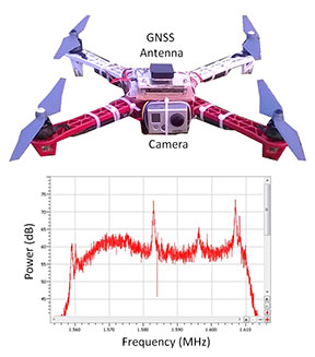 Figure 1 shows what happened to the GPS L1-band spectrum when a GoPro camera was installed on a quadcopter close to the GNSS antenna without sufficient shielding. The three peaks are exactly 24 MHz apart. This points to their being harmonics of a 24 MHz signal: the typical frequency for a MMC/SD logging interface.
An AsteRx4 receiver, which includes the AIM+ system, was selected for this setup. As well as mitigating the effects of interference, AIM+ includes a spectrum plot to view the RF input from the antenna in both time and frequency domains.
At the installation stage, the ability to view the RF spectrum is an invaluable tool for identifying the source of interference. Plus, it helps with determining the effectiveness of measures such as modifying the setup or adding shielding.
For the quadcopter installation in this example, the loss of RTK was readily diagnosed. The problem was solved by placing the camera in a shielded case. All this while the quadcopter was still in the workshop.
Figure 1 shows what happened to the GPS L1-band spectrum when a GoPro camera was installed on a quadcopter close to the GNSS antenna without sufficient shielding. The three peaks are exactly 24 MHz apart. This points to their being harmonics of a 24 MHz signal: the typical frequency for a MMC/SD logging interface.
An AsteRx4 receiver, which includes the AIM+ system, was selected for this setup. As well as mitigating the effects of interference, AIM+ includes a spectrum plot to view the RF input from the antenna in both time and frequency domains.
At the installation stage, the ability to view the RF spectrum is an invaluable tool for identifying the source of interference. Plus, it helps with determining the effectiveness of measures such as modifying the setup or adding shielding.
For the quadcopter installation in this example, the loss of RTK was readily diagnosed. The problem was solved by placing the camera in a shielded case. All this while the quadcopter was still in the workshop.
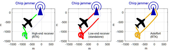 Figure 2 shows how a 10mW chirp jammer can knock out RTK positioning over more than 1 km in a high-end receiver.
Even a low-end consumer-grade L1 receiver, being less accurate and thus less sensitive, loses stand-alone positioning over several hundred meters.
With AIM+ activated, the AsteRx4 is able to maintain an RTK fix throughout the simulated flight. It also shows no degradation to its position variance.
Figure 2 shows how a 10mW chirp jammer can knock out RTK positioning over more than 1 km in a high-end receiver.
Even a low-end consumer-grade L1 receiver, being less accurate and thus less sensitive, loses stand-alone positioning over several hundred meters.
With AIM+ activated, the AsteRx4 is able to maintain an RTK fix throughout the simulated flight. It also shows no degradation to its position variance.
 February 13, 2017 - Septentrio GNSS technology continues to provide solutions for challenging situations.
Case in point? The Belgian dredging, environmental and engineering group DEME. They rely on the accuracy and reliability of the AsteRx family of precise GNSS positioning solutions from Septentrio.
DEME is using Septentrio’s AsteRx GNSS receivers to obtain centimeter-level accuracy for all their dredging and marine construction operations worldwide.
These receivers are designed to operate in difficult conditions. From ice-covered Arctic ports to the tropical climates of Southeast Asia; whether dredging a few meters from the coast line to constructing wind turbines kilometers out at sea.
February 13, 2017 - Septentrio GNSS technology continues to provide solutions for challenging situations.
Case in point? The Belgian dredging, environmental and engineering group DEME. They rely on the accuracy and reliability of the AsteRx family of precise GNSS positioning solutions from Septentrio.
DEME is using Septentrio’s AsteRx GNSS receivers to obtain centimeter-level accuracy for all their dredging and marine construction operations worldwide.
These receivers are designed to operate in difficult conditions. From ice-covered Arctic ports to the tropical climates of Southeast Asia; whether dredging a few meters from the coast line to constructing wind turbines kilometers out at sea.
 Your challenge, should you choose to accept it…
You’ve been asked to survey some points on the ground with centimeter-level accuracy. Feeling confident?
How about a few hundred points spread over 7.5 hectares (18.53 acres) and the job has to be done in one afternoon. Throw in the fact that the area you have to survey is in a quarry which has been closed off due to a recent landslide. Still feeling confident?
You should and here’s why.
Improvements in Unmanned Aerial Vehicle (UAV) technology combined with more compact high-end Global Navigation Satellite Systems (GNSS) receivers means that you no longer have to compromise on precision to measure in those hard-to-reach areas.
Your challenge, should you choose to accept it…
You’ve been asked to survey some points on the ground with centimeter-level accuracy. Feeling confident?
How about a few hundred points spread over 7.5 hectares (18.53 acres) and the job has to be done in one afternoon. Throw in the fact that the area you have to survey is in a quarry which has been closed off due to a recent landslide. Still feeling confident?
You should and here’s why.
Improvements in Unmanned Aerial Vehicle (UAV) technology combined with more compact high-end Global Navigation Satellite Systems (GNSS) receivers means that you no longer have to compromise on precision to measure in those hard-to-reach areas.
 UAVs have become more reliable and easier to work with: from programming flight paths to installing additional equipment on board, UAV applications are no longer confined to a limited group of specialists.
For a survey flight, your UAV will need to have installed: a high-resolution camera and a high-end GNSS receiver module. To fly the UAV through a pre-programmed flight plan, an autopilot flight controller is often included.
UAVs have become more reliable and easier to work with: from programming flight paths to installing additional equipment on board, UAV applications are no longer confined to a limited group of specialists.
For a survey flight, your UAV will need to have installed: a high-resolution camera and a high-end GNSS receiver module. To fly the UAV through a pre-programmed flight plan, an autopilot flight controller is often included.