Delivering high accuracy with GNSS, is it possible? Let’s say you need reliable accurate global positioning in your technology. You do some research and decide a multi-frequency GPS/GNSS[1] receiver is the solution. So, you order an evaluation kit.
Now, how do you get your receiver to deliver the high accuracy that it promises?
GNSS receivers rely on external corrections to compensate for various imperfections called GNSS errors to achieve decimeter or even centimeter level accuracy as fast as possible.
Correcting GNSS errors
GNSS based positioning is calculated using a method which, by itself, is limited in accuracy. The accuracy limitations are due to several errors caused by GNSS satellites as well as the Earth’s atmosphere.
GNSS satellites are essentially highly accurate synchronized clocks orbiting the Earth. These satellites constantly broadcast their positioning and timing information.
A GNSS user receiver gets signals from several of these “flying clocks” and calculates its distance to each satellite. When the receiver knows the distance to at least four satellites it can deduce its own position.
However, certain errors affect the accuracy of this position.
Even advanced clocks on board GNSS satellites experience minute drifts which cause clock errors.
As GNSS satellites orbit the Earth, their movement along the path is predictable. However, these predictions are not ideal, which results in what’s called orbit errors.
Plus, satellite equipment also introduces small signal errors. They model these errors as satellite biases.
Atmospheric errors
Additionally, there are atmospheric errors. As the signal passes through the Earth’s ionosphere (outer layer) and troposphere (layer near the Earth’s surface), it experiences distortions and delays.
Finally, the local environment around the receiver as well as the receiver itself can introduce errors. For example, satellite signals can reflect off buildings and tall structures, a phenomenon referred to as multipath.
A GNSS receiver cannot correct satellite and atmospheric errors by itself. It relies on data provided by an external source for these corrections.
Clock and orbit errors are satellite dependent, which means that they are the same around the world.
On the other hand, atmospheric errors depend on the path the signal takes as it travels from the satellites to the user. Therefore, they differ depending on the receiver’s location.
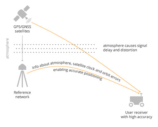
Use of a reference station, also known as a base station, can overcome both satellite and atmospheric errors.
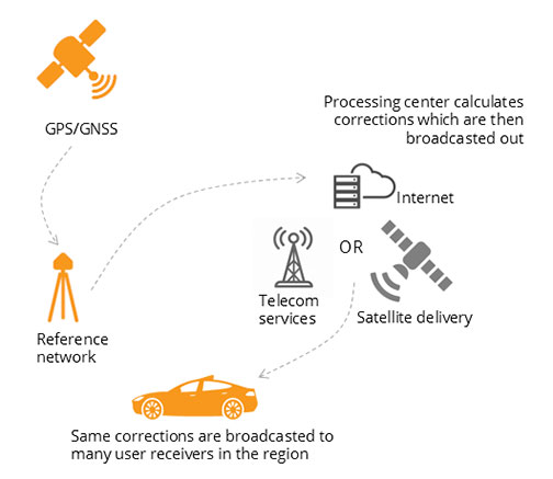
A reference station is a GNSS receiver which installs at a fixed and precisely known location. It estimates GNSS errors and sends them in the form of GNSS corrections to the user receiver (see image below). A reference network consists of interconnected reference receivers spread over an area.
A user receiver gets data, which it uses to correct satellite and atmospheric errors.
Robust receiver technology and careful operation can partially handle receiver-side errors. Depending on the type of corrections applied, it can take a few seconds to several minutes initialization time until high accuracy is achieved.
Types of corrections
Until recently, RTK and PPP were the established methods of providing GNSS corrections to user receivers.
Nowadays, the demand for high accuracy positioning is on the rise, paving the way for new positioning techniques such as the hybrid PPP-RTK.
RTK – the highest level of accuracy
In the Real Time Kinematic (RTK) method, a user receiver gets correction data from a single base station or from a local reference network. It then uses this data to eliminate most of the GNSS errors.
RTK is based on the principle that the base station and the user receiver are located close together (maximum 40 km or 25 miles apart) and therefore “see” the same errors.
For example, since the ionospheric delays are similar for both the user and the reference station, they can be cancelled out of the solution, allowing higher accuracy.
In the RTK method corrections are provided for a specific location.
In the PPP and PPP-RTK methods, they broadcast a correction model to a larger area but with slightly lower accuracy.
To transmit this correction model, they use a message format called Space State Representation (SSR). There is some confusion in the industry about the term “SSR”. It is occasionally a buzzword referring to traditional PPP services, as well.
PPP – globally accessible and accurate, but at a cost
The Precise Point Positioning (PPP) corrections contain only the satellite clock and orbit errors.
Since these errors are satellite specific, and thus independent of the user’s location, only a limited number of reference stations around the world are needed.
This method produces lower accuracy levels because it does not include atmospheric errors. Plus, it takes up to 20-30 minutes to initialize; which may not be practical for some applications.
Traditionally, the maritime industry uses PPP. Today, it expanded to various land applications such as agriculture, as a convenient way to get global GNSS corrections.
PPP-RTK, the best of both worlds?
PPP-RTK (a.k.a. SSR) is the latest generation of GNSS correction services. It combines near-RTK accuracy and quick initialization times with the broadcast nature of PPP.
A reference network, with stations about every 150 km (100 miles), collects GNSS data and calculates both satellite and atmospheric correction models.
As explained, atmospheric corrections are regional. Thus, it requires a denser reference network than for PPP. These corrections are broadcast to subscribers in the area via Internet, satellite or telecom services.
Subscribed receivers use the broadcasted correction model to deduce their location-specific corrections, resulting in sub-decimeter accuracy.
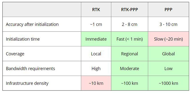
Comparing the three GNSS correction methods
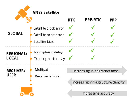
The table below compares the three correction methods, highlighting their strengths and weaknesses.
The infrastructure density and initialization time for all three methods vary with the different kinds of errors that are corrected, see image below.
The broadcast nature of PPP-RTK and PPP, as well as the lighter infrastructure that they require, makes these methods scalable for mass market applications.
Types of errors which are corrected by each of the three methods.
Some GNSS receivers also incorporate advanced positioning algorithms to compensate for receiver-side issues such as multipath, jamming and spoofing. This adds reliability and robustness to high accuracy positioning.
Getting GNSS Corrections
Modern industrial receivers often get their GNSS corrections via a subscription service. These corrections are delivered via Internet (using NTRIP protocol), satellite or 4G/5G.
Today, driven by the high accuracy demands of the automotive industry, automation and smart devices, there is a boom in the correction service market.
Automotive suppliers and many other new players are deploying infrastructure to set up services for centimeter-level positioning around the globe.
User receivers often get their GNSS corrections via a subscription service delivered via internet, satellite or 4G/5G.
PPP and PPP-RTK corrections can even transmit directly by the GNSS satellites, as in the Japanese CLAS service from the QZSS constellation, or in the planned High-Accuracy Service (HAS) from Galileo.
Depending on the network density and quality of the error modelling, different initialization times and accuracies can be achieved. This means that positioning quality can vary from one service provider to another.
Major telecom companies such as Deutsche Telekom as well as the Japanese Softbank and NTT are equipping their infrastructure with GNSS receivers to enable new corrections services.
3GPP, which provides specifications for mobile telephony including LTE, 4G and 5G, now covers broadcasting of GNSS satellite corrections in their mobile protocol.
Since reference receivers are becoming part of critical infrastructure, such as telecom towers, it is essential that they have a high level of security to protect them from potential jamming or spoofing attacks.
Which corrections are right for me?
The right correction service for your technology depends on your location and service area, your accuracy and reliability needs, as well as budget.
Because the corrections market keeps expanding, it is now more important than ever that integrators or GNSS manufacturers assist you in selecting the best correction method for your industrial application.
If you choose a GNSS receiver which does not “lock” you to a certain correction service, you are free to choose a correction method which is most suitable for your application and its location. Such “non-locking” open-interface receivers also offer customers flexibility to switch to another more beneficial service in the future, as correction methods keep evolving.
Footnote:
[1] Global Navigation Satellite System including the American GPS, European Galileo, Russian GLONASS, and Chinese BeiDou, Japan’s QZSS and India’s NavIC. These satellite constellations broadcast positioning information to receivers which use it to calculate their location.
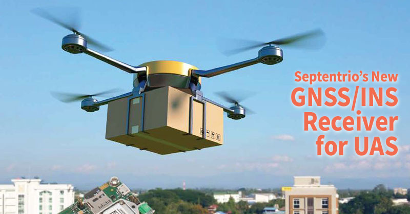
Recently, Septentrio introduced the AsteRx-i S UAS to their product line. This GNSS/INS receiver’s design is specifically for Unmanned Aerial Systems (UAS).
AsteRx-i S UAS combines GNSS technology with an industrial-grade inertial sensor. It provides high-accuracy, reliable positioning and 3D orientation (heading, roll, pitch) to aerial drones and other compact robotic systems.
Septentrio’s AsteRx-i S UAS builds on the success of their existing UAV products, AsteRx m2 and m2a UAS.
Designed for UAS
This credit card sized receiver easily integrates into any UAS and is compatible with popular autopilots such as Pixhawk and ArduPilot.
Plus, its light weight and low power consumption optimizes UAV battery life. The result? Longer flight times and improved productivity.
It is a single-package GNSS/INS product, with an on-board IMU (Inertial Measurement Unit) and standard connectors allowing flexibility of sensor choice.
“Quick receiver integration makes the lives of our customers easier. It also speeds up their system’s time-to-market,” said Danilo Sabbatini, Product Manager at Septentrio.
“Our goal was to combine a high-performance product with a simple and flexible plug-and-play integration design, suitable for any aerial system.”
Designed to Excel
Septentrio reliable centimeter-level positioning is based on multi-frequency, multi-constellation GNSS technology (GPS, GLONASS, Galileo, BeiDou, QZSS).
AsteRx-i S UAS combines a GNSS receiver with a high-quality IMU to deliver reliable positioning together with 3D orientation.
Septentrio’s unique GNSS – IMU integration algorithm provides continuous positioning during short GNSS outages (coasting) which can happen in flight near high structures, under bridges or during banking turns.
In aerial drones, where lots of electronics are crammed into a small space, neighboring devices can emit electromagnetic radiation which interferes with GPS and GNSS signals.
AIM+ offers protection against such interference resulting in faster set-up times and robust continuous operation. A built-in power spectrum plot allows users to analyze interference, helping locate its source and mitigating it.
Septentrio provides high-precision, multi-frequency, multi-constellation GPS/GNSS positioning technology for use in demanding applications. Reliable centimeter-level positioning enables machine autonomy and ensures operational continuity, efficiency and safety. Septentrio provides positioning solutions for professional applications in such industries as autonomous vehicles, robotics, construction, mapping, marine, logistics and unmanned aerial vehicles (UAVs).
AsteRx-i S joins Septentrio’s GNSS/INS product portfolio
The AsteRx-i S combines Septentrio’s compact, multi-frequency multi-constellation GNSS engine with ultralight external industrial grade MEMS based IMU.
Calibrated for wide temperature ranges, the AsteRx-i S delivers accurate and reliable GNSS/IMU integrated positioning to the cm-level as well as full attitude at high update rates and low latency.
Key benefits for users:
GNSS/INS positioning with 3D attitude: heading pitch and roll
AIM+ interference monitoring and mitigation system
High-update rate, low-latency positioning and attitude
Small & ultralight IMU (10 grams)
Robust calibration for wide temperature ranges
The AsteRx-i S is designed around demanding requirements for size, weight, power consumption and temperature variation. It is ideal for various applications such as inspection with UAV’s, UAS photogrammetry, automation, robotics, and logistics.
“We are delighted to broaden our AsteRx-i GNSS/INS solutions range, bringing maximum flexibility and choice to our customers. Whether for direct georeferencing in mapping applications with UAVs, for managing containers in a port or for innovative small robots in agriculture, the compactness, affordability and robustness of the AsteRx-i range allows our customers to focus on their success.” said Francesca Clemente, Product Manager at Septentrio.
Knowing the correct time is something we take for granted. But, who exactly decides the correct time in the first place? How does anyone go about determining the correct time? And, how does GPS fit in to the story?
To determine the time, BIPM in Paris relies on contributions from a worldwide collaboration of timing laboratories. Each of these laboratories maintain their own measure of time and compare it with GPS time.
One clock to rule them all
Timing labs employ precise clocks. To measure time precisely, Cesium atomic clocks and Hydrogen masers are among the most popular devices.
Although these clocks are very reliable — accurate to about 2 nanoseconds per day — small variations still occur. At BIPM in Paris, they compare the performance of clocks in timing labs from around the world. They use a weighted average of all contributions and calculate Coordinated Universal Time (UTC).
Interestingly, labs with better performing or more stable clocks receive more weight in the UTC calculation.
This means that real-time UTC is only an approximation… albeit a very accurate one. Thus, they determine the more precise calculation in retrospect.
The Circular-T journal, published monthly by BIPM, contains the small corrections. They apply these corrections to UTC for the previous month.
GPS receivers and time
Each timing lab contributing to UTC measures its own version of UTC. For example, UTCBrussels is the Belgian measure of UTC.
So how does BIPM compare the performance of all these different clocks?
It uses GPS receivers. Or, more accurately, GNSS (Global Navigation Satellite System) receivers which – in addition to GPS — track constellations, such as: GLONASS, Galileo, BeiDou and IRNSS.
The precise measurement of time is at the heart of every GPS receiver.
They determine the distances between satellite and receiver, used to calculate position, by measuring the transit times of the satellite signals to the receiver.
An error of 1 nanosecond in the transit time translates into an error of 30cm in the distance.
Flying clocks
The GPS satellite constellation uses its own precise measure of time called: GPS time. Each GPS satellite has its own, on-board set of atomic clocks. Thus, satellites are also very accurate flying clocks.
By tracking a GPS satellite, a receiver can record the time differences between its own receiver clock and the satellite clock, e.g. UTCBrussels – GPS time.
The time differences, along with other information, are in a data format called CGGTTS and sent to BIPM. Using CGGTTS and other data, BIPM compares a clock in Brussels with a clock in New York by subtracting the individual differences with GPS time. As such, this technique is known as “common view”.
UTCBrussels – UTCNew York = (UTCBrussels – GPS time) – (UTCNew York – GPS time).
The two GPS time terms above cancel each other out leaving the difference between UTCBrussels and UTCNew York.
Setting up a timing laboratory
In order to compare the atomic clocks used in timing labs around the world, they need to connect to a GPS timing receiver. A GPS timing receiver uses an external atomic clock instead of its own clock; which it does by using two output signals from the atomic clock:
a pulse every second synchronised to UTC (PPS IN) and
a 10 MHz frequency reference that is essentially a sine wave (REF IN)
Figure 3 depicts the basic ingredients of a timing laboratory.
However, to reach the nanosecond accuracy required, it takes a great deal of expertise and preparation.
Signal delays in all elements in the setup require accurate calibration. To do this, BIPM maintains a set of pre-calibrated travelling receivers as calibration references.
As well as providing 1/3 of the timing receivers used for the calculation of UTC, Septentrio also provides BIPM with timing receivers for calibration.
Pushing the boundaries of science
Beyond defining and disseminating UTC, GPS timing receivers are staking their place at the forefront of science.
For example, take the case of the T2K experiment. By precisely measuring the transit time of neutrinos between two locations, limits are placed on their mass. Thus, it sheds more light on the nature of these elusive particles.
At the other end of the size spectrum, the Very-Long-Baseline Interferometry (VLBI) technique uses radio telescopes at distant locations. These telescopes are linked together in networks by time-synching their observations using GPS common view. The resulting resolution is far in excess of anything that can be achieved by any single telescope on its own.
GPS technology continues to find new ways to improve our world and advance our knowledge of it.
GPS Spoofing: is your high-end receiver safe from an attack?
Threats from jammers have long worried GNSS users. And, now, a new GNSS bogeyman is here…spoofers. Unlike jamming, which attempts to block GNSS signals, spoofers are altogether far more sinister.
By replicating GNSS signals, a spoofer can fool a receiver into thinking that it’s elsewhere in either time or location.
And, given a growing reliance on GNSS technology for positioning and timing, it’s not hard to imagine the potential havoc a spoofing attack might cause.
$150 SDRs bring spoofing to the masses
Traditionally, spoofing is an expensive pursuit. A GPS simulator, with a price tag in the tens of thousands of dollars, is usually enough to put off most would-be spoofers.
But the now affordable price of this technology is changing the landscape.
In 2013, a team of researchers from the University of Texas commandeered a 213‑foot yacht using $3,000 worth of equipment.
The arrival of cheap Software Defined Radios (SDR) and open-source code availability is making spoofing more accessible.
Signs of spoofing
If a smartphone provides positioning, the first inkling of a spoofing attack is the phone reporting an obviously wrong location.
Figure 1shows an example of an attacker spoofing an iPhone6 into reporting its position at the top of Mount Everest.
It was harder to spoof an Acer Android phone. The Acer uses additional positioning information from WiFi and the cellular network.
During this test, the phone owner’s wife was alerted via Facebook that he had left the country.But, spoofing a trip to North Korea might have a slightly less amusing outcome.
In the case of high-end receivers that use multiple frequencies from several satellite constellations, spoofing is more challenging. Below are signs to look for if there is suspicion of spoofing.
1) The spoofed signal is visible in the RF spectrum
The low power of GPS signals means that they are barely discernible from the thermal noise background.
In order to spoof a receiver, the SDR signals are transmitted with a much higher power making them clearly visible above the background as Figure 2 shows.
2) Divergent code minus carrier behavior
Over short time frames, satellite distances measured using the code and carrier phase of the satellite signals should show very little difference – Figure 3 (upper panel).
This behavior is difficult to replicate. So, spoofed signals exhibit a difference that can increases rapidly over a short period of time – Figure 3 (lower panel).
3) Incomplete and inaccurate nav data
Spoofed satellite navigation data is often missing the GPS constellation almanac and is still only a vague match for the real navigation data.
4) Jamming of Glonass and/or L2
Spoofing techniques are advancing but at the moment, only the GPS L1 signal is spoofed so a common tactic is to additionally jam the L1 Glonass frequencies and the L2 band. This will manifest as a sudden fallback to a GPS only standalone mode.
What can receivers do about spoofing?
As shown, single-frequency, low-end devices and smartphones are relatively easy to spoof. High-end multi-frequency receivers aren’t so easy. These high-end receivers offer a number of tricks to detect spoofing.
However, in the event such a receiver detects spoofing, what exactly can it do?
1) Signal integrity alerting
High-end receivers have the option of employing spoofing flags. As such, the receiver can alert the user if it detects a spoofing attack directly in the RF spectrum or in the GPS measurements.
2) Frequency diversity
If the receiver detects spoofing on one frequency, it can switch to using measurements from other frequencies. Thereby, effectively ignoring the spoofed frequency.
Figure 4 shows this technique in action.
Three receivers are subject to GPS L1 spoofing. As the spoofer power increases, the Septentrio AsteRx4 receiver detects the spoof on L1. At this point, it switches from an L1/L2 to an L2/L5 PVT and successfully maintains an accurate position.
The other multi-frequency receiver also detects a problem. However, it has no alternative dual-frequency solution so simply stops outputting a PVT.
The L1-only module, with no detection mechanisms, switches to tracking the spoofed signal and its position gets spoofed.
3) Inertial sensor integration
An IMU device, either coupled to the receiver or mounted on the board itself, provides a unambiguous check for spoofing. In the presence of spoofing, IMUs can also provide input for an integrated PVT solution to mitigate the effects of spoofing.
Staying one step ahead
High-end GNSS receivers, particularly those employing spoofing detection and mitigation methods are still relatively safe from spoofers.
However, the increasing sophistication of both hardware — in the form of SDRs and open-source software — means there’s no room for complacency.
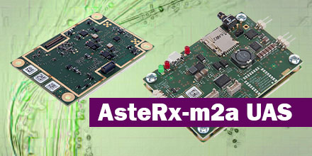
Septentrio launches the AsteRx-m2a and AsteRx-m2a UAS
This week, at Commercial UAV 2017, Septentrio announced the arrival of the AsteRx-m2a and AsteRx-m2a UAS GNSS OEM engines.
The two OEM boards bring the latest in precise and reliable multi-frequency, all-in-view RTK positioning and heading.
The boards also provide unmatched interference technology — all for the lowest power consumption of any comparable product on the market today.
AsteRx-m2a Advancements
Smaller than a credit card, the AsteRx-m2a and AsteRx-m2a UAS feature Septentrio’s pioneering AIM+ interference mitigation and monitoring system. AIM+ suppresses the widest variety of interferers — from continuous narrow-band signals to complex wide-band and pulsed jammers.
Increasing radio-frequency pollution plus the intrinsic danger of self-interference in compact systems such as UAS, are common problems. As such, interference mitigation is now vital for any UAS system using GNSS positioning.
Both boards bring high-precision positioning and attitude to any space-constrained application. Additionally, their ease-of-integration and high-update rate, low-latency output make both receivers ideal core components in any multi-sensor application.
Unmanned applications
AsteRx-m2a UAS is aimed specifically at unmanned applications bringing plug-and-play compatibility for autopilot systems such as ArduPilot and Pixhawk.
Event markers accurately synchronize camera shutter events with GNSS time. Plus, the board can power directly from the vehicle power bus via its wide-range input.
In addition, the AsteRx-m2a UAS works seamlessly with GeoTagZ Software. As such, it provides offline re-processed RTK accuracy without the need for either Ground Control Points or a real-time datalink.
“We’ve taken the hugely successful AsteRx-m2 and added a second antenna input for high-precision GNSS heading,” said Gustavo Lopez, OEM Product Manager at Septentrio. “No need to maneuver around in a figure of ‘8’ trying to initialize INS heading or find space or additional power for a separate INS module now. All you need is a second antenna and you’re good to go.”
Headquartered in Leuven, Belgium, Septentrio designs, manufactures and sells high-precision, multi-frequency, multi-constellation GPS/GNSS equipment for use in demanding applications. Septentrio receivers deliver consistently accurate and precise GNSS positioning scalable to centimeter-level and designed to perform solidly in the most challenging environments. Septentrio receivers are available as OEM boards, housed receivers and smart antennas.