05Jul
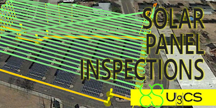
PV Solar Panel Field Inspection with UgCS Mission Planning Software
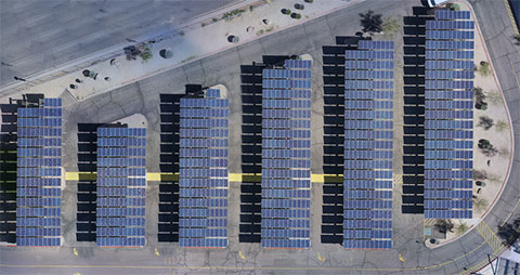
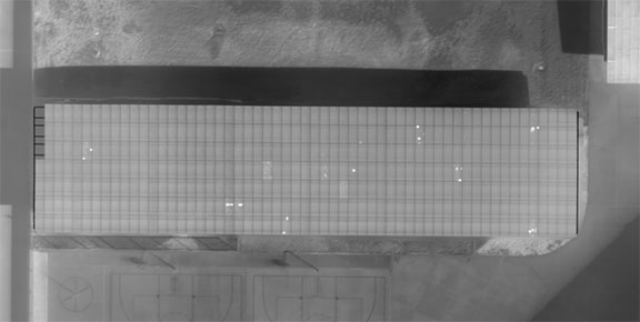
 Solar panel fields, like any other artificial infrastructure objects, require periodical inspections. Usually photovoltaic (PV) solar panel field inspection requires use of two sensors - infrared (IR) and daylight cameras, to detect faulty panels. Solar panels may heat up because of connection issues, physical damage or debris.
A drone equipped with a thermal camera is the best choice for solar panel field inspection. This method saves costs compared to manned aviation and saves time compared to visual control with handheld IR camera.
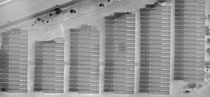
Semi-professional drones with changeable cameras like DJI Inspire are an option. However, switching out cameras means flight time is doubled. The first is a survey flight conducted with a daylight camera. The flight is then repeated after changing to an IR camera. To minimize time required for inspection usually both sensors (cameras) are used simultaneously. Such a payload requires a drone with enough lift-off capability.
Solar panel fields, like any other artificial infrastructure objects, require periodical inspections. Usually photovoltaic (PV) solar panel field inspection requires use of two sensors - infrared (IR) and daylight cameras, to detect faulty panels. Solar panels may heat up because of connection issues, physical damage or debris.
A drone equipped with a thermal camera is the best choice for solar panel field inspection. This method saves costs compared to manned aviation and saves time compared to visual control with handheld IR camera.
Semi-professional drones with changeable cameras like DJI Inspire are an option. However, switching out cameras means flight time is doubled. The first is a survey flight conducted with a daylight camera. The flight is then repeated after changing to an IR camera. To minimize time required for inspection usually both sensors (cameras) are used simultaneously. Such a payload requires a drone with enough lift-off capability.
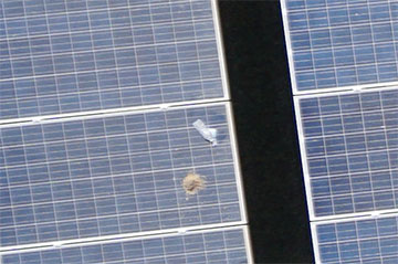
Detectable defects
The two major defects visible with IR camera are connection issues and physical damage. Connection issues occur, for example, when a panel or a string of panels are not connected to the system. As a result, power produced from the panel(s) cannot flow through the system and on to the grid. That power is converted to heat and the entire panel(s) will heat up slightly.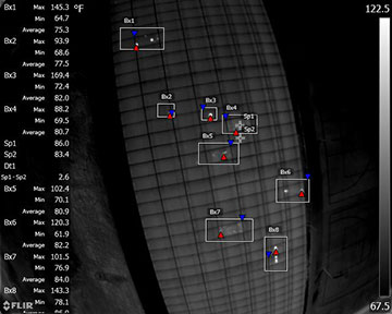
Solar Panel Field Inspection Mission Planning in UgCS
In general, solar panel field inspection missions with drones are planned the same way as standard UAV photogrammetry missions. The survey area is set and the route and camera settings are optimized to obtain the best result for data processing.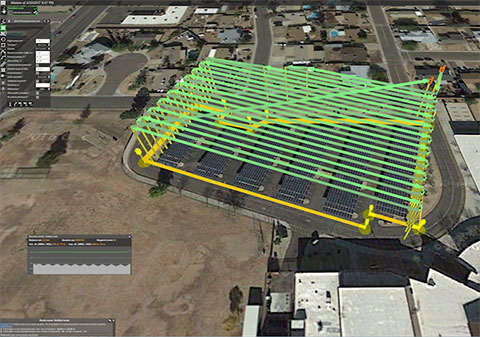
GSD selection
For photogrammetry, mission ground sampling distance (GSD) is defined by client and it is the main characteristic of survey’s output data. In case of solar panel inspection client has to define which defects have to be detected. To detect panels with connection issues GSD for IR images should be set 25 cm. To detect physical damage or hotspots smaller than whole panel the GSD should be set from 5-16 cm. For survey missions, when a drone carries IR and daylight cameras simultaneously, the GSD for daylight camera isn’t relevant. This is because it produces pictures with much better GSD than IR sensor because of the low resolution of thermal cameras. For example, an optical camera with a 16 mm lens to match the 7.5 mm FLIR lens will produce images with 1.3GSD while the FLIR images are at 15.7GSD. For solar panel survey missions, when a drone with changeable cameras is used set GSD > 2 cm - this will enable to detect even small debris on panels but will not produce thousands of images from flight.Camera position
Mostly camera are set to nadir position. In situations where a tracker system can't be positioned at a set angle or for some fixed array sites – based on the time of the day and sun position oblique setup can be used. Optimal angle of solar panels for thermal images is from 5 to 30 degrees to avoid reflection and inaccurate temperatures. If such images can’t be acquired with nadir camera position, the camera angle has to be adjusted to ensure pictures of panels in range from 5 to 30 degree angle.Data processing
Standard image data processing techniques can be used to stitch photos taken with daylight and IR cameras.