
Choosing the Right RF Filter for Your Application
 Choosing the right RF Filter for your application can feel like a daunting task. After all, there are numerous options available.
As such, when choosing an RF filter for your communications system, test and measurement setup, or RF module design, the best option depends on your specific application.
Below are some key parameters to help guide your decision:
- The frequency range(s) that shall pass through the filter (i.e., the passband)
- The frequency range(s) that shall be rejected by the filter (i.e., the stopband)
- The signal power level that will pass through, or be rejected by the filter
- The amount of attenuation allowable in the passband (i.e., insertion loss (IL))
- The amount of rejection required in the stopband(s)
- The limitations on the physical size of the filter
- The cost target for the filter
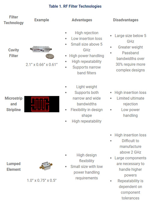
While there are many types or “topologies” of filters to choose from, the majority of NuWaves’ filter designs fall into three major categories: cavity, microstrip or stripline, and lumped element.
Cavity filters
Cavity filters provide the lowest insertion loss and greatest ultimate rejection of the three topologies and are capable of handling high levels of RF power (tens of watts to hundreds of watts).
At radio frequencies, the materials used in filter construction impact the performance of the filter. Printed circuit board (PCB) materials have dielectric losses that increase the insertion loss of the filter and reduces the Q-factor of the filter (how sharply the filter transitions from the passband to the stopband).
For cavity filters, the dielectric is air, which is essentially lossless. Additionally, cavity filters are constructed from metals such as steel, aluminum, or brass, which shield the signal within the filter from other signals and interference from the outside. This provides a high amount of ultimate attenuation.
The cost of a cavity filter, in general, is higher than that of other topologies. These filters are typically CNC machined, and require a skilled technician to properly tune the filter during assembly. See Table 1 below for the advantages and disadvantages of each topology.
Microstrip or stripline filters
Microstrip or stripline filters are printed on PCB substrates, using microstrip transmission lines (printed on the top or bottom layer of the PCB), or stripline transmission lines (printed on an internal layer of the PCB).
These filter topologies are good choices for filtering between gain stages, post frequency mixers to eliminate the image frequency, as well as output filters.
The ability to integrate the filter directly into the PCB greatly reduces implementation cost and simplifies the manufacturing process. [The real cost is in the designer’s labor]. Also, the filters may be printed on individual daughter boards and simply soldered to the main PCB.
The performance of the filter heavily depends on the PCB substrate. Low-cost FR-4 type substrates will perform adequately at frequencies up to 1 GHz. However, as frequency increases, the loss due to the substrate becomes a critical factor. Therefore, higher quality, low-loss microwave substrate is necessary at microwave frequencies (i.e., frequencies greater than 1 GHz).
The cost of microstrip or stripline filters can be quite inexpensive when designed into the PCB of the RF Module. Surface mount, drop-in, or connectorized modules will be more expensive, but less than cavity filters.
Microstrip filters suffer from low ultimate rejection (-25 dB to -40 dB) due to the fact that the microstrip traces are exposed on the outermost layer of the PCB. The ultimate rejection can be improved by enclosing the filter with an RF shield.
Stripline has a higher ultimate rejection because the traces are sandwiched between two groundplane layers inside the PCB. Substrate losses are greater with stripline than microstrip, because the traces are completely enclosed in substrate, where microstrip is half substrate, half air.
In general, microstrip and stripline filters can handle several tens of watts. Insertion loss values are typically 1 dB to 4 dB, depending on passband bandwidth (narrower bandwidth with have more loss), and the selectivity of the filter.
The physical size of these filters is dependent on frequency, where the traces are typically ¼ wavelength long. This dependency makes the filters impractically large below UHF frequencies, unless miniaturization techniques are employed.
Lumped element filters
Lumped element filters are a good option for filtering below 1 GHz, where cavity filters and microstrip/stripline filters may be prohibitively large.
The term “lumped element” refers to the use of capacitors and inductors (i.e., physical components or “lumps”) to create the filter response.
The physical size of lumped element filters is mostly driven by the power handing required. A low power handling requirement, such as < 10 mW, may be constructed of the smallest components available (0201 or 0402 sized components for example). While a requirement for hundreds of watts would require inductors and capacitors capable of handling the high current and voltage of the system.
Similar to the microstip/stripline filters, lumped element filters may be integrated into the PCB design, integrated as a surface mount daughterboard, as a drop-in component, or a connectorized package for internal or external integration.
The cost of a lumped element filter is similar to that of microstrip or stripline filters.
Passband insertion loss of lumped element filters varies greatly depending on the quality of components (Q-factor), selectivity required, and type of filter response (highpass, lowpass, bandpass, etc.).
Therefore, the passband insertion loss is typically in the range of 0.5 dB to 5 dB. Ultimate rejection also varies, from up to 70 dB for a filter with a traditional Butterworth or Chebyshev response, to 25 to 35 dB for a bandpass filter with an elliptical response (high selectivity and low passband insertion loss (~1.5 dB typical) with lower ultimate rejection).
A disadvantage to lumped element filters is high frequency performance, as capacitors and inductors are limited by the self-resonance frequency of the component. Self-resonance frequencies become a design concern above 1 GHz, and very few components have self-resonance frequencies above 6 GHz.
Choosing an RF Filter
RF Filtering is a key component of any communications system to eliminate interference and out-of-band emissions. There are many types of filters to choose from, but by identifying the key parameters that are important to your design, the choices can be narrowed down significantly.
Shop NuWaves Engineering’s complete line of RF Filters at Unmanned Systems Source.